Yamaha VXS10S Owner's Manual - Page 1
Yamaha VXS10S Manual
 |
View all Yamaha VXS10S manuals
Add to My Manuals
Save this manual to your list of manuals |
Page 1 highlights
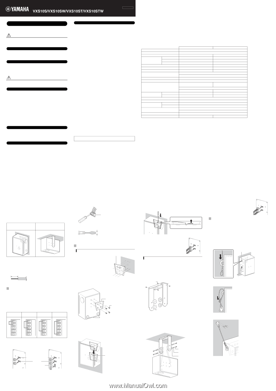
Surface Mount Speaker Owner's Manual PRECAUTIONS PLEASE READ CAREFULLY BEFORE PROCEEDING * Please keep this manual in a safe place for future reference. WARNING Always follow the basic precautions listed below to avoid the possibility of serious injury or even death from electrical shock, short-circuiting, damages, fire or other hazards. These precautions include, but are not limited to, the following: Do not open • This device contains no user-serviceable parts. Do not open the device or attempt to disassemble the internal parts or modify them in any way. If it should appear to be malfunctioning, discontinue use immediately and have it inspected by qualified Yamaha service personnel. Water warning • Do not expose the device to rain, use it near water or in damp or wet conditions, or place on it any containers (such as vases, bottles or glasses) containing liquids which might spill into any openings. If any liquid such as water seeps into the device, have the device inspected by qualified Yamaha service personnel. CAUTION Always follow the basic precautions listed below to avoid the possibility of physical injury to you or others, or damage to the device or other property. These precautions include, but are not limited to, the following: Location • Do not place the device in an unstable position where it might accidentally fall over. • Do not place the device in a location where it may come into contact with corrosive gases or salt air. Doing so may result in malfunction. • Construction work should be carried out in accordance with constructionrelated law and always by a professional constructor. If the device installation requires construction work, make sure to observe the following precautions. - Choose mounting hardware and an installation location that can support the weight of the device. - Avoid locations that are exposed to constant vibration. - Use the required tools to install the device. - Inspect the device periodically. • When transporting or moving the device, always use two or more people. Attempting to lift the device by yourself may damage your back, result in other injury, or cause damage to the device itself. Connections • Before connecting the device to a power amplifier, turn off the power for all devices. Before turning the power on or off for all devices, set all volume levels to minimum. • Use only speaker cables for connecting speakers to the speaker connectors. Use of other types of cables may result in fire. Maintenance • Do not wipe the outer packaging with benzine, thinner, or synthetic detergent and do not use electrical contact cleaner. These may damage the outer packaging and dissolve the parts. ZG14070 English Handling caution • Avoid inserting or dropping foreign objects (paper, plastic, metal, etc.) into holes of the grille. If this happens, have the device inspected by qualified Yamaha service personnel. • Do not operate the device if the sound is distorting. Prolonged use in this condition could cause overheating and result in fire. • When choosing a power amplifier for use with this device, make sure that the output power of the amplifier is lower than the power capacity of this device (see SPECIFICATIONS). Even if the output power of the amplifier is lower than the power capacity of this device (PGM), use of excessive input signals resulting in clipping may cause damage to the device. Malfunction or fire may occur especially when the following sounds or noises are generated: - feedback, when using a microphone - continuous and extreme volume sound from a musical instrument - extreme continuous distorted sound - noise caused by plugging/unplugging the cable while the amplifier is turned on NOTICE To avoid the possibility of malfunction/damage to the product or damage to other property, follow the notices below. ●Handling and Maintenance • Do not place vinyl, plastic or rubber objects on the device, since this might discolor the cabinet. • When cleaning the device, use a dry and soft cloth. Do not use paint thinners, solvents, cleaning fluids, or chemical-impregnated wiping cloths. • Condensation can occur in the device due to rapid, drastic changes in ambient temperature-when the device is moved from one location to another, or air conditioning is turned on or off, for example. Using the device while condensation is present can cause damage. If there is reason to believe that condensation might have occurred, leave the device for several hours until the condensation has completely dried out. • Be sure to observe the amplifier's rated load impedance (see SPECIFICATIONS), particularly when connecting speakers in parallel. Connecting an impedance load outside the amplifier's rated range can damage the amplifier. • When connecting the speakers with high impedance, be sure that the output total of each speaker does not exceed the rated output of the power amplifier. • ABOUT THE PROTECTION CIRCUIT This speaker system has an internal protection circuit that shuts off the speaker unit when an excessive input signal is applied. If the speaker unit emits no sound, reduce the volume level of the amplifier immediately. The sound will return automatically in several seconds. • Place the speaker on a flat and smooth surface. ●About This Manual The illustrations as shown in this manual are for instructional purposes only, and may appear somewhat different from those on your device. Yamaha cannot be held responsible for damage caused by improper use or modifications to the device. UNPACKING Unpack the contents and confirm that all the following items are included. • Speaker × 1 • Bracket base × 1 • Mounting bracket × 1 • Captive washer screw × 4 • Rubber spacer × 4 (14 mm thickness) • Hexagon bolt × 4 • Spring washer × 4 • Flat washer × 4 • Safety wire × 1 • Owner's Manual (this manual) * Screws/bolts to fasten the bracket onto the wall and speaker cables are not included. SPECIFICATIONS VXS10S/VXS10SW VXS10ST/VXS10STW Type Subwoofer, Bass reflex Component 10" (25 cm) Cone driver, Dual voice coil Nominal impedance 8 Ω + 8 Ω - Power rating NOISE 100 W + 100 W - (IEC, 100h) *1 PGM 200 W + 200 W - MAX Sensitivity (1W, 1m) *2 Maximum SPL (Calculated, 1m) *3 Frequency range (-10 dB) *2 400 W + 400 W 96 dB SPL 125 dB SPL 45 Hz - 250 Hz - 96 dB SPL - 45 Hz - 250 Hz Subwoofer filter Network: Low-pass filter 6 dB/Oct, 200 Hz Acoustic filter: Low-pass filter 6 dB/Oct, 200 Hz Satellite filter Satellite impedance Network: High-pass filter 6 dB/Oct, 200 Hz 8 Ω load per satellite output recommended *4 Connector Euroblock (4 pin) × 1: Input (CH1: +/-, CH2: +/-) Euroblock (4 pin) × 1: Input (input: +/-, loop-thru: +/-) Euroblock (4 pin) × 1: Satellite output (ST1: +/-, ST2: +/-) - Euroblock (5 pin) × 1: transformer taps Transformer taps 70 V - 200 W, 100 W, 50 W, 25 W 100 V - 200 W, 100 W, 50 W Overload protection Full-range power limiting to protect network and transducers Magnetically shielded No Enclosure Shape Rectangle Cabinet material MDF Finish VXS10S/VXS10ST: Black (PVC, approximate value: Munsell N3) VXS10SW/VXS10STW: White (PVC, approximate value: Munsell 3.5PB9.0/1) Dimensions (Speaker only) 260 × 500 × 389 mm (10.2" × 19.7" × 15.3") Net weight (Speaker only) 16.5 kg (36.4 lb) 19.5 kg (43.0 lb) *1: Pink noise with 6 dB crest factor. *2: Half-space (2π) *3: Calculated based on power rating and sensitivity, exclusive of power compression. *4: Impedance lower limit (per satellite output) VXS10S/VXS10SW: 4 Ω, VXS10ST/VXS10STW: 8 Ω Specifications and descriptions in this owner's manual are for information purposes only. Yamaha Corp. reserves the right to change or modify products or specifications at any time without prior notice. Since specifications, equipment or options may not be the same in every locale, please check with your Yamaha dealer. The dimensions are shown overleaf. INSTALLING THE SPEAKER When installing the speaker on the floor, attach the rubber spacers to the underside of the speaker to provide support. When installing the speaker on a wall or ceiling, use the included brackets or optional U-bracket UB-DXR8. Ensure that the wall/ceiling is sufficiently strong. This package does not include the mounting hardware to install the included brackets/safety wire or the UB-DXR8. If you are not sure what materials are required for installation, consult a specialist. An installed speaker is shown below. Install the bracket as shown. Wall installation (using included brackets) Ceiling installation (using optional bracket UB-DXR8) WARNING • Do not use the included brackets for ceiling installation. • Do not use the UB-DXR8 for wall installation. Pre-installation (Preparation of the cable) Use stranded wire for cables attached to the Euroblock connector. Strip their insulation as shown in the figure and connect them. About 7 mm (0.3 in.) NOTE Do not plate stranded wires by solder. Doing so will cause the wire to break. 1 CONNECT THE WIRING TO THE CONNECTOR Connect the cable from the amplifier to the "INPUT" socket, and the cable being connected to other speakers to the "SATELLITE SPEAKERS" socket. A signal input to CH1 of INPUT is output from ST1 of SATELLITE SPEAKERS, and signal input to CH2 of INPUT is output from ST2 of SATELLITE SPEAKERS. For VXS10ST/VXS10STW, connect the included 5-pin Euroblock connector as shown below and set the appropriate wattage when using 100 V/70 V line. 100V/× 70V/200W 100V/200W 70V/100W 100V/100W 70V/50W 100V/50W 70V/25W NOTE No setting should be made for 100 V line, as shown in the far left illustration. 1 Remove the Euroblock connector from the speaker. 2 After loosening the terminal screws of the Euroblock connector with a flat-blade screwdriver, insert the cable into each terminal and tighten the screws. Make sure that cables cannot be pulled out. Euroblock connector NOTE Use a flat-blade screwdriver with a blade less than 3 mm (0.1 in.). Less than 3 mm (0.1 in.) 3 (VXS10ST/VXS10STW only) Plug the 5-pin Euroblock connector into the TRANSFORMER SETTINGS socket. 2 INSTALL THE SPEAKER Installing on the wall (using the included brackets) 1 Place the bracket base on the wall and mark the position for screws/bolts. The diameter of seven holes for screw/bolt (not included) is ø6.5 mm. 2 Make holes in the wall for the bolts, as required, and feed the bolts through the holes. 3 Affix the bracket base on the wall. The narrow edge of the bracket base should be oriented downward. Bracket base 4 Attach the mounting bracket to the speaker with the included screws with captive washer. The narrow edge of the mounting bracket should be oriented downward. Mounting bracket Captive washer screw Rubber spacer 5 Attach the two rubber spacers to the bottom edge of the speaker. Make sure the spacers are located near the outer edge; otherwise, they will impede installation on the bracket base in the next step. 6 Slide the speaker down onto the bracket base until it locks in place. NOTE Be sure to perform this work with two or more people. SATELLITE SPEAKERS INPUT TRANSFORMER SETTINGS VXS10S/VXS10SW VXS10ST/VXS10STW Lock To detach the mounting bracket from the bracket base, release the lock of the mounting bracket with a long flat-blade driver and lift the speaker. NOTE Be sure to perform this work with two or more people. 5 Plug the Euroblock connectors into the SATELLITE SPEAKERS and INPUT sockets. 7 Plug the Euroblock connectors into the SATELLITE SPEAKERS and INPUT sockets. Installing on the ceiling (using the optional UB-DXR8) To determine the appropriate size of the UB-DXR8, download the "U BRACKET OWNER'S MANUAL" from the following manual library site. http://www.yamaha.co.jp/manual/ 1 Assemble two L-shaped brackets into a U-shape using the M5 × 10 screws included with the UB-DXR8 as shown below. Peel off the sheet from each rubber spacer (14 mm thickness; included with the speaker), and attach the spacers to the inside of each bracket arm aligning the holes so that the hexagon bolts can be inserted. M5 × 10 3 ATTACH THE SAFETY WIRE This section explains how to attach the included safety wire. NOTE • Make sure to take measures to prevent the speaker from falling down in the event of a installation failure. • When installing the safety wire to the wall, install it higher than the wire's attachment point on the speaker, with as little slack as possible. • If the safety wire is too short, prepare another wire appropriate for the speaker weight and installation conditions. If the wire is too long, should the speaker fall, the wire may snap as a result of too much strain. 1 Pass the safety wire through the eyebolt on the rear of the speaker. Eyebolt 2 Pass the bracket of the safety wire through the loop on the other end, and pull tight up against the eyebolt. Rubber spacer 2 Make sure that the width of the U bracket matches the speaker width. 3 Affix the U bracket on the ceiling using appropriate mounting hardware. 4 Use the hexagon bolts, spring washers and flat washers included with the speaker to attach the speaker to the UB-DXR8. NOTE Be sure to perform this work with two or more people. 3 Affix the bracket of the safety wire to the wall. Hexagon bolt Spring washer Flat washer
-
 1
1 -
 2
2
 |
 |