Yamaha YHT-670 Quick Connection Guide - Page 1
Yamaha YHT-670 Manual
 |
View all Yamaha YHT-670 manuals
Add to My Manuals
Save this manual to your list of manuals |
Page 1 highlights
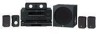
Quick-Connect Poster YHT-670 Home Theater in a Box Yamaha created this package to greatly enhance your audio and home theater enjoyment. This Quick-Connect Poster will help you get started. Follow the steps to connect the speakers first. Then connect your DVD Player and other components. Refer to your Owner's Manuals as well as those that came with your other components for complete instructions and precautions. Be sure that all components are not plugged in while making connections. You will need the following which are not included in the package: Phillips screwdriver, wire cutter/stripper, optional for wall mounting: brackets, toggle bolts, molly anchor screws or sheet metal screws. 1 Your System 2 7 89 Room Layout 5 6 Inspect Contents After unpacking, inspect the contents to confirm you have the above items: two front speakers, two surround speakers, one center speaker, subwoofer, HTR-5950 A/V Receiver with remote control, DV-C6860 DVD Player with remote control, speaker wire, 8 subwoofer RCA cable, 9 audio/video RCA cable. Also included, but not shown, are AM and FM antennas and related Owner's Manuals. 3 4 Speaker Placement After connection of the speakers place them so they appear in the approximate positions as shown in the diagram above. 5 4 3/16" Connect Speaker Wire Cut speaker wire 6 to appropriate lengths for all speaker connections. Connect speaker wire for front speakers , and surround speakers .The positive (+) side of the wire with the white stripe attaches to the red terminal. The negative (-) side attaches to the black terminal. (See your HTR-5950 Owner's Manual for more information on speaker wire connections.) Mount Surround Speakers (optional) Fasten mounting screws into a firm wall or wall support. Leave 1/4" space between head and wall. Hang the keyholes on the speaker backs on the protruding screws. WARNING Please contact a reliable source about the best type of hardware for your particular wall's construction. Secure installation is the purchaser's responsibility. See your Owner's Manual for additional precautions. 5 11/16" HTR-5950 Receiver Speaker Connections Connect Front Speakers Positive (+) side of the wire with white stripe attaches to (+) terminal. Negative (-) side attaches to (‑) terminal. CAUTION Receiver must not be plugged in while connecting speakers. 6 Connect Center Speaker Wire Connect Center Speaker Wire as shown. The positive (+) side of the wire with the white stripe attaches to the red terminal. The negative (-) side attaches to the black terminal. Place all speakers in desired location as shown in Step 2, Room Layout. HTR-5950 Receiver 7 8 CAUTION Receiver must not be plugged in while connecting speakers. Connect Surround Speakers Positive (+) side of the wire with white stripe attaches to (+) terminal. Negative (-) side attaches to (‑) terminal. YST-SW012 Subwoofer 9 AM Loop Antenna Indoor FM Antenna HTR-5950 Receiver HTR-5950 Receiver Connect Center Speaker Positive (+) side of the wire with white stripe attaches to (+) terminal. Negative (-) side attaches to (‑) terminal. CAUTION Receiver must not be plugged in while connecting speakers. HTR-5950 Receiver Subwoofer Connection Connect RCA Cable Connect RCA cable 8 to subwoofer . Set subwoofer VOLUME control to half-way mark and POWER to OFF. Connect RCA cable to receiver from subwoofer. WARNING Receiver must not be plugged in while connecting speakers. Antenna Connection Connect Antennas to Receiver Locate AM loop antenna and indoor FM antenna. Keeping receiver unplugged, connect as shown. For more information about obtaining clear reception and grounding, see your Owner's Manual.
-
 1
1 -
 2
2
 |
 |
