ZyXEL GS1100-24 User Guide - Page 9
Hardware Description and Connection, 2.1 Rear Panel, 2.1.1 Rear Panel Power Connection - switch
 |
View all ZyXEL GS1100-24 manuals
Add to My Manuals
Save this manual to your list of manuals |
Page 9 highlights
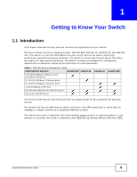
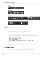
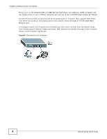
CHAPTER 2 Hardware Description and Connection 2.1 Rear Panel The power receptacle is located on the rear panel of the Switch. Refer to the power supply requirements on the panel. Figure 5 Rear Panel GS1100-8HP GS1100-16 GS1100-24 GS1100-24E 2.1.1 Rear Panel Power Connection Connect one end of the supplied power cord or power adaptor to the power receptacle on the back of the Switch and the other end to the appropriate power source. For the GS1100-8HP, GS1100-16 and GS1100-24E, use the POWER ON/OFF switch to have the Switch power on or off. 2.2 Front Panel The front panel of the Switch includes the auto-negotiating 10 Base-T/100 Base-TX/1000 Base-T RJ-45 ports and the LEDs. GS1100 Series User's Guide 9
-
 1
1 -
2
-
3
-
 4
4 -
 5
5 -
 6
6 -
 7
7 -
 8
8 -
 9
9 -
 10
10 -
 11
11 -
 12
12 -
 13
13 -
 14
14 -
15
-
16
-
17
-
18
-
19
-
20
-
21
-
22
-
23
-
24
 |
 |

GS1100 Series User’s Guide
9
C
HAPTER
2
Hardware Description and Connection
2.1
Rear Panel
The power receptacle is located on the rear panel of the Switch. Refer to the power supply
requirements on the panel.
Figure 5
Rear Panel
2.1.1
Rear Panel Power Connection
Connect one end of the supplied power cord or power adaptor to the power receptacle on the back
of the Switch and the other end to the appropriate power source.
For the GS1100-8HP, GS1100-16 and GS1100-24E, use the
POWER ON/OFF
switch to have the
Switch power on or off.
2.2
Front Panel
The front panel of the Switch includes the auto-negotiating 10 Base-T/100 Base-TX/1000 Base-T
RJ-45 ports and the LEDs.
GS1100-16
GS1100-24
GS1100-8HP
GS1100-24E