eMachines D620 Service Guide - Page 71
Removing the LCD Brackets
 |
View all eMachines D620 manuals
Add to My Manuals
Save this manual to your list of manuals |
Page 71 highlights
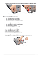
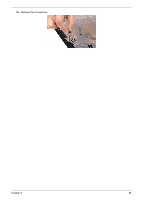
17. Turn the LCD panel over, then detach the acetic tapes holding the FPC cable to the edge of the LCD panel and detach the acetic tape securing the FPC connector. 18. Disconnect the FPC cable from the LCD panel. Removing the LCD Brackets 1. See "Removing the Battery Pack" on page 51. 2. See "Removing the Lower Cover" on page 51. 3. See "Removing the Lower Cover" on page 51. 4. See "Removing the Fan Module" on page 59. 5. See "Removing the CPU Heatsink Module" on page 60. 6. See "Removing the CPU" on page 61. 7. See "Removing the Middle Cover" on page 62. 8. See "Removing the Keyboard" on page 63. 9. See "Removing the LCD Module" on page 64. 10. See "Removing the LCD Bezel" on page 77. 11. See "Removing the Inverter Board" on page 78. 12. See "Removing the LCD with Brackets" on page 79. Chapter 3 81
-
 1
1 -
2
-
3
-
4
-
5
-
6
-
7
-
8
-
9
-
10
-
11
-
12
-
13
-
14
-
15
-
16
-
17
-
18
-
19
-
20
-
21
-
22
-
23
-
24
-
25
-
26
-
27
-
28
-
29
-
30
-
31
-
32
-
33
-
34
-
35
-
36
-
37
-
38
-
39
-
40
-
41
-
42
-
43
-
44
-
45
-
46
-
47
-
48
-
49
-
50
-
51
-
52
-
53
-
54
-
55
-
56
-
57
-
58
-
59
-
60
-
61
-
62
-
63
-
64
-
65
-
 66
66 -
 67
67 -
 68
68 -
 69
69 -
 70
70 -
 71
71 -
 72
72 -
 73
73 -
 74
74 -
 75
75 -
 76
76 -
77
-
78
-
79
-
80
-
81
-
82
-
83
-
84
-
85
-
86
-
87
-
88
-
89
-
90
-
91
-
92
-
93
-
94
-
95
-
96
-
97
-
98
-
99
-
100
-
101
-
102
-
103
-
104
-
105
-
106
-
107
-
108
-
109
-
110
-
111
-
112
-
113
-
114
-
115
-
116
-
117
-
118
 |
 |
