eMachines T3882 NG3 Hardware Reference - Page 175
Replacing the front I/O panel - heatsink
 |
View all eMachines T3882 manuals
Add to My Manuals
Save this manual to your list of manuals |
Page 175 highlights
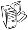
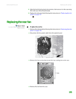
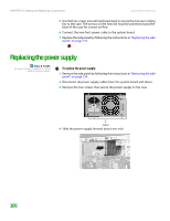
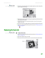
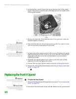
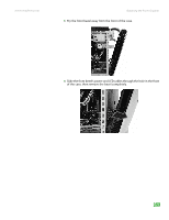
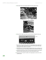
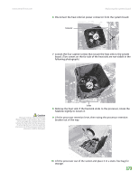
CHAPTER 13: Adding and Replacing Components www.emachines.com 4 Loosen the four captive screws that secure the heat sink to the system board. (Two screws on the far side of the heat sink are not visible in the following photograph.) Caution The heat sink has Thermal Interface Material (TIM) on the bottom. Be careful not to damage this material when you remove the heat sink from the processor. If removing the heat sink also pulls the processor out of the processor socket, the processor could be damaged. Caution The heat sink has Thermal Interface Material (TIM) located on the bottom of it. Use caution when you unpack the heat sink so you do not damage the TIM. Screws 5 Remove the heat sink. If the heatsink sticks to the processor, rotate the heatsink slightly to loosen it. 6 Place the heat sink over the processor, lining up the four captive screws with the four posts surrounding the processor. 7 Loosely screw in the captive screws on the corners of the heat sink, gently tightening diagonal screws (screw in one screw, then the screw located diagonally to the first screw). Do not fully tighten one screw before tightening another. 8 Gradually and equally tighten each captive screw until each is firmly tightened. Do not over-tighten the screws. 9 Connect the new heat sink fan's power connector to the system board. 10 Replace the side panel by following the instructions in "Replacing the side panel" on page 157. Replacing the front I/O panel Important The color and shape of your replacement component's front cover may vary from your original component. Tips & Tricks To make it easier to reconnect the cables to the system board later, make note of each connector's location as you disconnect it. 168 To replace the front I/O panel: 1 Remove the side panel by following the instructions in "Removing the side panel" on page 154. 2 Disconnect the front bezel's power and LED cables from the system board.
-
 1
1 -
2
-
3
-
4
-
5
-
6
-
7
-
8
-
9
-
10
-
11
-
12
-
13
-
14
-
15
-
16
-
17
-
18
-
19
-
20
-
21
-
22
-
23
-
24
-
25
-
26
-
27
-
28
-
29
-
30
-
31
-
32
-
33
-
34
-
35
-
36
-
37
-
38
-
39
-
40
-
41
-
42
-
43
-
44
-
45
-
46
-
47
-
48
-
49
-
50
-
51
-
52
-
53
-
54
-
55
-
56
-
57
-
58
-
59
-
60
-
61
-
62
-
63
-
64
-
65
-
66
-
67
-
68
-
69
-
70
-
71
-
72
-
73
-
74
-
75
-
76
-
77
-
78
-
79
-
80
-
81
-
82
-
83
-
84
-
85
-
86
-
87
-
88
-
89
-
90
-
91
-
92
-
93
-
94
-
95
-
96
-
97
-
98
-
99
-
100
-
101
-
102
-
103
-
104
-
105
-
106
-
107
-
108
-
109
-
110
-
111
-
112
-
113
-
114
-
115
-
116
-
117
-
118
-
119
-
120
-
121
-
122
-
123
-
124
-
125
-
126
-
127
-
128
-
129
-
130
-
131
-
132
-
133
-
134
-
135
-
136
-
137
-
138
-
139
-
140
-
141
-
142
-
143
-
144
-
145
-
146
-
147
-
148
-
149
-
150
-
151
-
152
-
153
-
154
-
155
-
156
-
157
-
158
-
159
-
160
-
161
-
162
-
163
-
164
-
165
-
166
-
167
-
168
-
169
-
 170
170 -
 171
171 -
 172
172 -
 173
173 -
 174
174 -
 175
175 -
 176
176 -
 177
177 -
 178
178 -
 179
179 -
 180
180 -
181
-
182
-
183
-
184
-
185
-
186
-
187
-
188
-
189
-
190
-
191
-
192
-
193
-
194
-
195
-
196
-
197
-
198
-
199
-
200
-
201
-
202
-
203
-
204
-
205
-
206
-
207
-
208
-
209
-
210
-
211
-
212
-
213
-
214
 |
 |