3Com 2126-G User Guide - Page 3
Nstalling, Witch
 |
UPC - 662705494197
View all 3Com 2126-G manuals
Add to My Manuals
Save this manual to your list of manuals |
Page 3 highlights
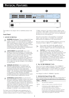
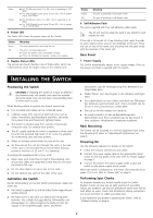
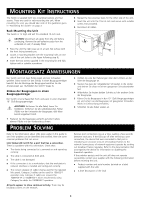
Green Yellow ■ For 10/100 ports (ports 1 to 24) - Link is operating at 100 Mbps ■ For 1000 (Gigabit) ports (ports 25 and 26) - Link is operating at 1000 Mbps ■ For 10/100 ports (ports 1 to 24) - Link is operating at 10 Mbps ■ For 1000 (Gigabit) ports (ports 25 and 26) - Link is operating at 10/100 Mbps 4 Power LED The Power LED shows the power status of the Switch: Status Green Off Meaning The unit is powered on and ready for use. The unit is not receiving power: ■ Check the power cord is connected correctly. ■ If the unit still does not operate, contact your supplier. 5 Duplex Status LEDs The second and fourth (bottom) row of Status LEDs, which are colored yellow, show the duplex status of the related ports: Status Yellow Off Meaning The port is operating in full-duplex mode. The port is operating in half-duplex mode. 6 Self-Adhesive Pads The unit is supplied with four self-adhesive rubber pads. You do not need to apply the pads if you intend to rack mount the unit. If the unit is to be part of a free standing stack, apply the pads to each marked corner area on the underside of the unit. Place the unit on top of the lower unit, ensuring that the pads locate with the recesses of the lower unit. Rear Panel 7 Power Supply The Switch automatically adjusts to the supply voltage. Only use the power cord that is supplied with the Switch. INSTALLING THE SWITCH Positioning the Switch CAUTION: If installing the Switch in a stack of different ! size Baseline units, the smaller units must be installed above the larger ones. Do not have a free-standing stack of more than six units. When deciding where to position the Switch ensure that: „ It is accessible and cables can be connected easily. „ Cabling is away from sources of electrical noise such as radios, transmitters and broadband amplifiers, and away from power lines and fluorescent lighting fixtures. „ The Switch is situated away from sources of electrically conductive dust, for example laser printers. „ The AC supply used by the Switch is separate to those used by units that generate high levels of AC noise, for example air conditioning units and laser printers. „ Water or moisture cannot enter the case of the unit. „ Air flow around the unit and through the vents in the side of the case is not restricted (3Com recommends that you provide a minimum of 25 mm (1 in.) clearance). To prolong the operational life of your units: „ Never stack units more than six high if free-standing, and ensure that cables are supported so that they do not cause the stack to fall over. „ Do not place objects on top of any unit or stack. „ Do not obstruct any vents at the sides of the case. Aufstellen des Switch Bei der Entscheidung wo Sie den Switch positionieren, stellen Sie sicher das: „ Der Switch zugänglich ist und die Kabel leicht angeschlossen werden können. „ Die Kabel nicht in der nähe von elektrischen Störquellen befinden. Das schließt Aufzugsschächte, Mikrowellen und Klimaanlagen ein. Elektromagnetische Felder können die Signale in den Kupferleitungen stören, und Fehler verursachen, was die Verlangsamung Ihres Netzwerkes zur Folge haben kann. „ Weder Wasser noch Feuchtigkeit in das Gehäuse eindringen kann. „ Die Luftzirkulation um den Switch und durch die Öffnungen des Gehäuses nicht behindert wird. 3Com empfiehlt das Sie 25mm (1 Inch) Zwischenraum sicherstellen. „ Die Luft so frei wie möglich von Staub ist. „ Es unwahrscheinlich ist das die Betriebstemperatur überschritten wird. 3Com empfiehlt das Sie den Switch in einer sauberen, klimatisierten Umgebung installieren. Rack Mounting The Switch can be mounted in a 19-inch equipment rack using the Mounting Kit. Refer to "Mounting Kit Instructions" on page 4. Powering On Use the following sequence to power on the Switch: 1 Check the network connections and cables. 2 Connect the power supply cable to the appropriate power socket on the rear panel of the unit; refer to "Power Supply" on page 3. 3 Connect the plug to the power supply outlet socket and switch on the power supply at the socket. When the switch is powered on, the Power LED should be lit on green. If it is not, refer to "Power LED" on page 3. Performing Spot Checks At frequent intervals you should visually check the Switch. Regular checks can give you an early warning of a possible failure; any problems can then be attended to when there will be least effect on users. Check that all external cabling connections are secure and that no cables are pulled taut. If you experience any problems operating the Switch, refer to "Problem Solving" on page 6. 3
-
 1
1 -
 2
2 -
 3
3 -
 4
4 -
 5
5 -
 6
6 -
 7
7 -
 8
8 -
 9
9
 |
 |