ASRock 775XFire-RAID User Manual
ASRock 775XFire-RAID Manual
 |
View all ASRock 775XFire-RAID manuals
Add to My Manuals
Save this manual to your list of manuals |
ASRock 775XFire-RAID manual content summary:
- ASRock 775XFire-RAID | User Manual - Page 1
775XFire-RAID User Manual Version 1.1 Published February 2006 Copyright©2006 ASRock INC. All rights reserved. 1 - ASRock 775XFire-RAID | User Manual - Page 2
any form or by any means, except duplication of documentation by the purchaser for backup purpose, without written consent of ASRock Inc. Products and corporate names appearing in this manual may or may not be registered trademarks or copyrights of their respective companies, and are used only for - ASRock 775XFire-RAID | User Manual - Page 3
1.1 Package Contents 5 1.2 Specifications 6 1.3 Supported PCI Express VGA Card List for AGI Express Slot (PCI Express x 4 9 1.4 Motherboard Layout 10 1.5 HD 8CH I/O Panel 11 2 Installation 12 2.1 Screw Holes 12 2.2 Pre-installation Precautions 12 2.3 CPU Installation 13 2.4 Installation of - ASRock 775XFire-RAID | User Manual - Page 4
47 3.6 Security Screen 47 3.7 Exit Screen 48 4 Software Support 49 4.1 Install Operating System 49 4.2 Support CD Information 49 4.2.1 Running Support CD 49 4.2.2 Drivers Menu 49 4.2.3 Utilities Menu 49 4.2.4 "LGA 775 CPU Installation Live Demo" Program .. 49 4.2.5 Contact Information 49 - ASRock 775XFire-RAID | User Manual - Page 5
modifications of this manual occur, the updated version will be available on ASRock website without further notice. You may find the latest VGA cards and CPU support lists on ASRock website as well. ASRock website http://www.asrock.com 1.1 Package Contents ASRock 775XFire-RAID Motherboard (ATX Form - ASRock 775XFire-RAID | User Manual - Page 6
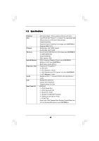
Slot Audio LAN Rear Panel I/O - ATX Form Factor: 12.0-in x 8.6-in, 30.5 cm x 21.8 cm - LGA 775 for Intel® Pentium® 4 / Celeron® D, supporting Cedar Mill processors (in 775-land LGA package) - FSB 800/533 MHz - Supports Hyper-Threading Technology (see CAUTION 1) - Supports EM64T CPU - Northbridge - ASRock 775XFire-RAID | User Manual - Page 7
SLI/XFIRE power connector - CD in header - Front panel audio connector - 2 x USB 2.0 headers (support 4 USB 2.0 ports) (see CAUTION 7) - 4Mb AMI BIOS - AMI Legal BIOS - Supports "Plug and Play" - ACPI 1.1 Compliance Wake Up Events - Supports jumperfree - Drivers, Utilities, AntiVirus Software - CPU - ASRock 775XFire-RAID | User Manual - Page 8
to the "Supported PCI Express VGA Card List for AGI Express Slot (PCI Express x 4)" on page 9. For the proper installation of PCI Express VGA card, please refer to the installation guide on page 18. 6. For microphone input, this motherboard supports both stereo and mono modes. For audio output, this - ASRock 775XFire-RAID | User Manual - Page 9
1.3 Supported PCI Express VGA Card List for AGI Express Slot (PCI Express x 4) (for Windows 2000/Windows XP) Graphics Chip updates of the supported PCI Express VGA card list for AGI Express slot (PCI Express x 4), please visit our website for details. ASRock website: http://www.asrock.com/support - ASRock 775XFire-RAID | User Manual - Page 10
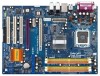
Motherboard BIOS Super I/O PCI EXPRESS RoHS 775XFire-RAID PCIE1 PCIE2 1 AGI_EXPRESS IDE1 1 CLRCMOS1 CMOS Battery 7.1CH HD PCIEX1_EN4 PCIEX1_EN3 PCIEX1_EN2 PCIEX1_EN1 PCI 1 PCI LAN PCI 2 AUDIO Connector (ATXPWR1) 4 775-Pin CPU Socket 5 North Bridge Controller 6 CPU Fan Connector (CPU_FAN1) - ASRock 775XFire-RAID | User Manual - Page 11
table below for connection details in accordance with the type of speaker you use. TABLE for Audio Output Connection Audio Output Channels Front Speaker Rear Speaker Central / Bass (No. 7) (No. 4) (No. 5) 2 V -- -- 4 V V -- 6 V V V 8 V V V Side Speaker (No. 3) ---V * If you - ASRock 775XFire-RAID | User Manual - Page 12
775XFire-RAID is an ATX form factor (12.0" x 8.6", 30.5 x 21.8 cm) motherboard. Before you install the motherboard, study the configuration of your chassis to ensure that the motherboard fits into it. Make sure to unplug the power cord before installing or removing the motherboard. Failure - ASRock 775XFire-RAID | User Manual - Page 13
the installation of Intel 775-LAND CPU, please follow the steps below. 775-Pin Socket Overview Before you insert the 775-LAND CPU into the socket, please check if the CPU surface is unclean or if there is any bent pin on the socket. Do not force to insert the CPU into the socket if above situation - ASRock 775XFire-RAID | User Manual - Page 14
to use the cap tab to handle and avoid kicking off the PnP cap. 2. This cap must be placed if returning the motherboard for after service. Step 4. Close the socket: Step 4-1. Rotate the load plate onto the IHS. Step 4-2. While pressing down lightly on load plate, engage the load lever. Step - ASRock 775XFire-RAID | User Manual - Page 15
Heatsink This motherboard is equipped with 775-Pin socket that supports Intel 775-LAND CPU. Please adopt the type of heatsink and cooling fan compliant with Intel 775-LAND CPU to dissipate heat. Before you installed the heatsink, you need to spray thermal interface material between the CPU and the - ASRock 775XFire-RAID | User Manual - Page 16
2.5 Installation of Memory Modules (DIMM) 775XFire-RAID motherboard provides four 240-pin DDRII (Double Data Rate II) DIMM slots, and supports Dual Channel Memory Technology. For dual channel configuration, you always need to install identical (the same brand, speed, size and chip-type) DDRII DIMM - ASRock 775XFire-RAID | User Manual - Page 17
matches the break on the slot. notch break notch break The DIMM only fits in one correct orientation. It will cause permanent damage to the motherboard and the DIMM if you force the DIMM into the slot at incorrect orientation. Step 3. Firmly insert the DIMM into the slot until the retaining - ASRock 775XFire-RAID | User Manual - Page 18
cards. For the information of the compatible PCI Express VGA cards, please refer to the "Supported PCI Express VGA Card List card to the chassis with screws. 2.7 Dual Graphics Feature This motherboard supports Dual Graphics Technology. When installing the add-on VGA cards to this motherboard - ASRock 775XFire-RAID | User Manual - Page 19
Operation Guide This motherboard supports CrossFireTM feature. CrossFireTM technology offers the most advantageous means available of combining multiple high performance Graphics Processing feature is only supported with Windows XP with Service Pack 2; it may be supported with other OS in the future - ASRock 775XFire-RAID | User Manual - Page 20
, we use Radeon X850XT as the example graphics card. For other CrossFireTM cards that ATI has released or will release in the future, please refer to ATI graphics card manuals for detailed installation guide. Step 1. Adjust the jumpers on this motherboard to enable AGI Express slot (PCI Express - ASRock 775XFire-RAID | User Manual - Page 21
series. Step 5. Correctly connect the DVI-DMS cable to the monitor connector and two graphics cards that you install. (If you install two standard Radeon (CrossFireTM Ready) graphics cards to this motherboard, please skip this step.) DVI-DMS cable DMS connector DVI connector P Standard Radeon - ASRock 775XFire-RAID | User Manual - Page 22
DVI of the compatible standard Radeon (CrossFireTM Ready) graphics card. Step 6. Power on your computer and boot into OS. Step 7. Remove the ATI driver if you have any VGA driver installed in your system. The Catalyst Uninstaller is an optional download. We recommend using this utility to uninstall - ASRock 775XFire-RAID | User Manual - Page 23
card drivers to your system, and restart your computer. Then you will find "ATI Catalyst Control Center" on your desktop (ATI Catalyst driver graphics card and one compatible standard Radeon (CrossFireTM Ready) graphics card to this motherboard but not two Radeon CrossFireTM Edition graphics cards - ASRock 775XFire-RAID | User Manual - Page 24
Display Feature This motherboard supports Surround Display upgrade. With the external add-on PCI Express VGA card, you can easily enjoy the benefits of Surround Display feature. For the detailed instruction, please refer to the document at the following path in the Support CD: ..\ Surround Display - ASRock 775XFire-RAID | User Manual - Page 25
) (39-pin IDE1, see p.10 No. 9) PIN1 IDE1 connect the blue end connect the black end to the motherboard to the IDE devices 80-conductor ATA 66/100 cable Note: Please refer to the instruction of your IDE device vendor for the details. Serial ATAI Connectors (SATA_0: see p.10, No. 15) (SATA_1 - ASRock 775XFire-RAID | User Manual - Page 26
2 additional USB 2.0 ports. This header supports an optional wireless transmitting and receiving infrared module. This connector allows you to receive stereo audio input from sound sources such as a CD-ROM, DVD-ROM, TV tuner card, or MPEG card. Front Panel Audio Header (9-pin HD_AUDIO1) (see p.10 - ASRock 775XFire-RAID | User Manual - Page 27
, but the panel wire on the chassis must support HDA to function correctly. Please follow the instruction in our manual and chassis manual to install your system. 2. If you use AC'97 audio panel, please install it to the front panel audio header as below: A. Connect Mic_IN (MIC) to MIC2_L - ASRock 775XFire-RAID | User Manual - Page 28
SLI/XFIRE Power Connector (4-pin SLI/XFIRE_POWER1) (see p.10 No. 31) SLI/XFIRE_POWER1 It is not necessary to use this connector, but please connect it with a hard disk power connecor when two graphics cards are plugged to this motherboard at the same time. Game Port Header (15-pin GAME1) (see p. - ASRock 775XFire-RAID | User Manual - Page 29
2.13 Hot Plug and Hot Swap Functions for SATA HDDs 775XFire-RAID motherboard supports Hot Plug and Hot Swap functions for SATA Devices. NOTE What is Hot Plug Function? If the SATA HDDs are NOT set for RAID configuration, it is called "Hot Plug" for the action to insert and remove the SATA HDDs while - ASRock 775XFire-RAID | User Manual - Page 30
in the Support CD, "Guide to SATA Hard Disks Installation and RAID Configuration", which is located in the folder at the following path: .. \ RAID Installation Guide STEP 4: Install Windows 2000 / Windows XP / Windows XP 64-bit OS on your system. After making a SATA driver diskette and using - ASRock 775XFire-RAID | User Manual - Page 31
or "Intel(R) 82801FR SATA RAID Controller (Desktop ICH6R-Windows XP64)" for Windows XP 64-bit. 5. Finish the Windows installation and install all necessary drivers. 6. Install the Intel(R) Matrix Storage Manager software via the CD-ROM included with your motherboard or after downloading it from the - ASRock 775XFire-RAID | User Manual - Page 32
XP 64-bit OS on your system. After making a SATA driver diskette, you can start to install Windows 2000 / Windows XP / Windows XP 64-bit on your system. At the beginning of Windows setup, press F6 to install a third-party SCSI or RAID driver. When prompted, insert a floppy disk containing the Intel - ASRock 775XFire-RAID | User Manual - Page 33
the BIOS SETUP UTILITY to configure your system. The BIOS FWH chip on the motherboard stores the BIOS SETUP UTILITY. You may run the BIOS SETUP off and then back on. Because the BIOS software is constantly being updated, the following BIOS setup screens and descriptions are for reference purpose - ASRock 775XFire-RAID | User Manual - Page 34
Overview System Time System Date [14:00:09] [Mon 12/12/2005] BIOS Version : 775XFire-RAID BIOS P1.00 Processor Type : Intel (R) CPU 3.40 GHz (64bit supported) Processor Speed : 3400 MHz Microcode Update : F34/17 Cache Size : 1024KB Total Memory DDRII 1 DDRII 2 DDRII 3 DDRII 4 : 256MB - ASRock 775XFire-RAID | User Manual - Page 35
Defaults Save and Exit Exit v02.54 (C) Copyright 1985-2005, American Megatrends, Inc. CPU Host Frequency While entering setup, BIOS auto detects the present CPU host frequency of this motherboard. The actual CPU host frequency will show in the following item. Boot Failure Guard Enable or disable - ASRock 775XFire-RAID | User Manual - Page 36
of this motherboard. CPU Thermal Throttling You may select [Enabled] to enable P4 CPU internal thermal control mechanism to keep the CPU from overheated. Hyper Threading Technology To enable this feature, it requires a computer system with an Intel Pentium®4 processor that supports Hyper-Threading - ASRock 775XFire-RAID | User Manual - Page 37
BIOS SETUP UTILITY Advanced Chipset Configuration DRAM Frequency [Auto] Flexibility Option [Disabled] Configure DRAM Timing by SPD [Enabled] DRAM CAS# Latency [Auto] Boot Graphic Adapter Priority [PCI/PCIE] OnBoard HD Audio Auto] is selected, the motherboard will detect the memory module(s) - ASRock 775XFire-RAID | User Manual - Page 38
or [PCIE/PCI] as the boot graphic adapter priority. The default value is [PCI/PCIE]. OnBoard HD Audio Select [Auto], [Enabled] or [Disabled] for the onboard HD Audio feature. If you select [Auto], the onboard HD Audio will be disabled when PCI Sound Card is plugged. Front Panel Control Select [Auto - ASRock 775XFire-RAID | User Manual - Page 39
3.3.3 ACPI Configuration BIOS SETUP UTILITY Advanced ACPI Configuration Suspend To RAM Restore on AC or disable the Sus pend-to-RAM feature. Select [Auto] will enable this feature if the system supports it. Restore on AC/Power Loss This allows you to set the power state after an unexpected AC/ - ASRock 775XFire-RAID | User Manual - Page 40
BIOS does not have these advantages. 2. Only AHCI and RAID modes support Hot Plug function. When [Compatible] is selected Combined Option , SATA2 will not work. Because Intel® ICH6R south bridge only supports four IDE devices under legacy OS (Windows NT), you have to choose [SATA 0, SATA 1, SATA 2, - ASRock 775XFire-RAID | User Manual - Page 41
IDE ARMD (ATAPI Removable Media Device), such as MO. LBA/Large Mode Use this item to select the LBA/Large mode for a hard disk > 512 MB under DOS and Windows; for Netware and UNIX user, select [Disabled] to disable the LBA/Large mode. 41 - ASRock 775XFire-RAID | User Manual - Page 42
maximize the IDE hard disk data transfer rate. 3.3.5 PCIPnP Configuration BIOS SETUP UTILITY Advanced Advanced PCI / PnP Settings WARNING: Setting wrong to keep the default value unless the installed PCI expansion cards' specifications require other settings. PCI IDE BusMaster Use this item to - ASRock 775XFire-RAID | User Manual - Page 43
3.3.6 Floppy Configuration In this section, you may configure the type of your floppy drive. BIOS SETUP UTILITY Advanced Floppy Configuration Floppy A [1.44 MB 312"] Select the type of floppy drive connected to the system. +F1 F9 F10 ESC Select Screen Select Item Change Option General Help - ASRock 775XFire-RAID | User Manual - Page 44
Parallel Port Address Use this item to set the address for the onboard parallel port or disable it. Configuration options: [Disabled], [378], and [278]. Parallel Port Mode Use this item to set the operation mode of the parallel port. The default value is [ECP+EPP]. If this option is set to [ECP+EPP - ASRock 775XFire-RAID | User Manual - Page 45
controller. USB 2.0 Support Use this item to enable or disable the USB 2.0 support. Legacy USB Support Use this item to enable or disable the support to emulate legacy of the CPU temperature, motherboard temperature, CPU fan speed, chassis fan speed, and the critical voltage. BIOS SETUP UTILITY - ASRock 775XFire-RAID | User Manual - Page 46
( C) The default value of tolerance is [2], which means the error of the target CPU temperature will be within 2 C. Target Fan Speed Use this option to set the target the boot settings and the boot priority. Main Advanced BIOS SETUP UTILITY H/W Monitor Boot Security Exit Boot Settings Boot - ASRock 775XFire-RAID | User Manual - Page 47
you may set or change the supervisor/user password for the system. For the user password, you may also clear it. BIOS SETUP UTILITY Main Advanced H/W Monitor Boot Security Exit Security Settings Supervisor Password : Not Installed User Password : Not Installed Change Supervisor Password - ASRock 775XFire-RAID | User Manual - Page 48
and exit setup?" Select [OK] to save the changes and exit the BIOS SETUP UTILITY. Discard Changes and Exit When you select this option, it message, "Discard changes and exit setup?" Select [OK] to exit the BIOS SETUP UTILITY without saving any changes. Discard Changes When you select this option - ASRock 775XFire-RAID | User Manual - Page 49
This motherboard is equipped with Intel LGA 775 socket, which is a new CPU socket interface that Intel has released. Since it has several tiny pins, whcih are easily to be damaged by improper handling, ASRock sincerely presents you a clear installation guide through this "LGA 775 CPU Installation
-
 1
1 -
 2
2 -
 3
3 -
 4
4 -
 5
5 -
 6
6 -
 7
7 -
8
-
9
-
10
-
11
-
12
-
13
-
14
-
15
-
16
-
17
-
18
-
19
-
20
-
21
-
22
-
23
-
24
-
25
-
26
-
27
-
28
-
29
-
30
-
31
-
32
-
33
-
34
-
35
-
36
-
37
-
38
-
39
-
40
-
41
-
42
-
43
-
44
-
45
-
46
-
47
-
48
-
49
 |
 |

1
775XFire-RAID
User Manual
Version 1.1
Published February 2006
Copyright©2006 ASRock INC. All rights reserved.