ASRock 890FX Deluxe5 User Manual
ASRock 890FX Deluxe5 Manual
 |
View all ASRock 890FX Deluxe5 manuals
Add to My Manuals
Save this manual to your list of manuals |
ASRock 890FX Deluxe5 manual content summary:
- ASRock 890FX Deluxe5 | User Manual - Page 1
890FX Deluxe5 User Manual Version 1.0 Published January 2011 Copyright©2011 ASRock INC. All rights reserved. 1 - ASRock 890FX Deluxe5 | User Manual - Page 2
ASRock. ASRock assumes no responsibility for any errors or omissions that may appear in this manual. With respect to the contents of this manual, ASRock does not provide warranty USA ONLY The Lithium battery adopted on this motherboard contains Perchlorate, a toxic substance controlled in Perchlorate - ASRock 890FX Deluxe5 | User Manual - Page 3
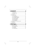
Hot Plug Feature and Operation Guide 39 2.14 Driver Installation Guide 41 2.15 Installing Windows® 7 / 7 64-bit / VistaTM / VistaTM 64-bit / XP / XP 64-bit With RAID Functions 41 2.15.1 Installing Windows® XP / XP 64-bit With RAID Functions 41 2.15.2 Installing Windows® 7 / 7 64-bit / VistaTM - ASRock 890FX Deluxe5 | User Manual - Page 4
Health Event Monitoring Screen 59 3.6 Boot Screen 60 3.7 Security Screen 61 3.8 Exit Screen 62 4 . Software Support 63 4.1 Install Operating System 63 4.2 Support CD Information 63 4.2.1 Running Support CD 63 4.2.2 Drivers Menu 63 4.2.3 Utilities Menu 63 4.2.4 Contact Information 63 4 - ASRock 890FX Deluxe5 | User Manual - Page 5
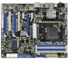
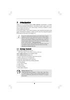
information about the model you are using. www.asrock.com/support/index.asp 1.1 Package Contents ASRock 890FX Deluxe5 Motherboard (ATX Form Factor: 12.0-in x 9.6-in, 30.5 cm x 24.4 cm) ASRock 890FX Deluxe5 Quick Installation Guide ASRock 890FX Deluxe5 Support CD 1 x Ultra ATA 66/100/133 IDE Ribbon - ASRock 890FX Deluxe5 | User Manual - Page 6
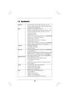
Platform CPU Chipset Memory Expansion Slot Audio LAN - ATX Form Factor: 12.0-in x 9.6-in, 30.5 cm x 24.4 cm - All Solid Capacitor design (100% Japan-made high-quality Conductive Polymer Capacitors) - Support for Socket AM3+ processors - Support for Socket AM3 processors: AMD PhenomTM II X6 - ASRock 890FX Deluxe5 | User Manual - Page 7
in/Front Speaker/Microphone (see CAUTION 6) - 6 x SATA3 6.0 Gb/s connectors by AMD SB850, support RAID (RAID 0, RAID 1, RAID 0+1 and RAID 5), NCQ, AHCI and "Hot Plug" functions - 2 x SATA3 6.0 Gb/s connectors by Marvell SE9120, support NCQ, AHCI and "Hot Plug" functions - 2 x Rear USB 3.0 ports by - ASRock 890FX Deluxe5 | User Manual - Page 8
Legal BIOS with GUI support - Supports "Plug and Play" - ACPI 1.1 Compliance Wake Up Events - Supports jumperfree - SMBIOS 2.3.1 Support - CPU, VCCM, NB, SB Voltage Multi-adjustment Support CD - Drivers, Utilities, AntiVirus Software (Trial Version), AMD OverDriveTM Utility, ASRock Software - ASRock 890FX Deluxe5 | User Manual - Page 9
This motherboard supports Untied Overclocking Technology. Please read "Untied Overclocking Technology" on page 44 for details. 3. This motherboard supports Dual Channel Memory Technology. Before you implement Dual Channel Memory Technology, make sure to read the installation guide of memory modules - ASRock 890FX Deluxe5 | User Manual - Page 10
embedded in Flash ROM. This convenient BIOS update tool allows you to update system BIOS without entering operating systems first like MS-DOS or Windows®. With this utility, you can press key during the POST or press key to BIOS setup menu to access ASRock Instant Flash. Just launch this - ASRock 890FX Deluxe5 | User Manual - Page 11
is detected, the system will automatically shutdown. Before you resume the system, please check if the CPU fan on the motherboard functions properly and unplug the power cord, then plug it back again. To improve heat dissipation, remember to spray thermal grease between the CPU and the heatsink - ASRock 890FX Deluxe5 | User Manual - Page 12
Super I/O 890FX Deluxe5 SATA3_8 PCIE4 Support 8-Core CPU SATA3 6Gb/s PCI Express 2.0 PCI2 ErP/EuP Ready Front USB 3.0 1394a RoHS NEC USB 3.0 PCIE5 COM1 1 SATA3_7 FLOPPY1 PLED PWRBTN 1 HDLED RESET PANEL 1 USB3_1_2 SATA3_5_6 AMD SB850 Chipset SATA3_3_4 SATA3_1_2 32Mb BIOS PWRBTN RSTBTN - ASRock 890FX Deluxe5 | User Manual - Page 13
Ports (USB45) 5 Side Speaker (Gray) 6 Rear Speaker (Black) 7 Central / Bass (Orange) 8 Line In (Light Blue) ** 9 Front Speaker (Lime) 14 13 12 11 10 Microphone (Pink) 11 USB 3.0 Ports (USB23) 12 IEEE 1394 Port (IEEE 1394) 13 eSATA3 Connector 14 USB 2.0 Ports (USB67) 15 USB 2.0 Ports (USB01) 16 - ASRock 890FX Deluxe5 | User Manual - Page 14
To enable Multi-Streaming function, you need to connect a front panel audio cable to the front panel audio header. After restarting your computer, you will find "Mixer" tool on your system. Please select "Mixer ToolBox" , click "Enable playback multi-streaming", and click "ok". Choose "2CH", " - ASRock 890FX Deluxe5 | User Manual - Page 15
or remove any component, ensure that the power is switched off or the power cord is detached from the power supply. Failure to do so may cause severe damage to the motherboard, peripherals, and/or components. 1. Unplug the power cord from the wall socket before touching any component. 2. To avoid - ASRock 890FX Deluxe5 | User Manual - Page 16
Triangle To The Socket Corner Small Triangle STEP 4: Push Down And Lock The Socket Lever 2.2 Installation of CPU Fan and Heatsink After you install the CPU into this motherboard, it is 8). For proper installation, please kindly refer to the instruction manuals of the CPU fan and the heatsink. 16 - ASRock 890FX Deluxe5 | User Manual - Page 17
of Memory Modules (DIMM) This motherboard provides four 240-pin DDR3 (Double Data Rate 3) DIMM slots, and supports Dual Channel Memory Technology. DDR3_B2; White slots; see p.12 No.10), so that Dual Channel Memory Technology can be activated. This motherboard also allows you to install four DDR3 - ASRock 890FX Deluxe5 | User Manual - Page 18
Installing a DIMM Please make sure to disconnect power supply before adding or removing DIMMs or the system break The DIMM only fits in one correct orientation. It will cause permanent damage to the motherboard and the DIMM if you force the DIMM into the slot at incorrect orientation. Step - ASRock 890FX Deluxe5 | User Manual - Page 19
install PCI Express graphics cards to support CrossFireXTM function. PCIE5 (PCIE power cord is unplugged. Please read the documentation of the expansion card and make necessary hardware settings for the card before you start the installation. Step 2. Remove the system unit cover (if your motherboard - ASRock 890FX Deluxe5 | User Manual - Page 20
Currently CrossFireXTM feature is supported with Windows® XP with Service Pack 2 / VistaTM / 7 OS. 3-way CrossFireXTM and Quad CrossFireXTM feature are supported with Windows® VistaTM / 7 OS only. Please check AMD website for ATITM CrossFireXTM driver updates. 1. If a customer incorrectly configures - ASRock 890FX Deluxe5 | User Manual - Page 21
Bridge Interconnects on the top of Radeon graphics cards. (CrossFire Bridge is provided with the graphics card you purchase, not bundled with this motherboard. Please refer to your graphics card vendor for details.) CrossFire Bridge or Step 3. Connect the DVI monitor cable to the DVI connector - ASRock 890FX Deluxe5 | User Manual - Page 22
Bridge to connect Radeon graphics cards on PCIE4 and PCIE5 slots. (CrossFireTM Bridge is provided with the graphics card you purchase, not bundled with this motherboard. Please refer to your graphics card vendor for details.) 22 - ASRock 890FX Deluxe5 | User Manual - Page 23
CrossFireTM Bridge Step 5. Connect the DVI monitor cable to the DVI connector on the Radeon graphics card on PCIE2 slot. (You may use the DVI to D-Sub adapter to convert the DVI connector to D-Sub interface, and then connect the D-Sub monitor cable to the DVI to D-Sub adapter.) 23 - ASRock 890FX Deluxe5 | User Manual - Page 24
prior to installation. Please check AMD website for ATITM driver updates. Step 3. Step 4. Step 5. Install the required drivers to your system. For Windows® XP OS: A. ATITM recommends Windows® XP Service Pack 2 or higher to be installed (If you have Windows® XP Service Pack 2 or higher installed in - ASRock 890FX Deluxe5 | User Manual - Page 25
is used only for identification or explanation and to the owners' benefit, without intent to infringe. * For further information of ATITM CrossFireXTM technology, please check AMD website for updates and details. 25 - ASRock 890FX Deluxe5 | User Manual - Page 26
Display Feature This motherboard supports Surround Display upgrade. With the external add-on PCI Express VGA cards, you can easily enjoy the benefits of Surround Display feature. For the detailed instruction, please refer to the document at the following path in the Support CD: ..\ Surround Display - ASRock 890FX Deluxe5 | User Manual - Page 27
to the motherboard connect the black end to the IDE devices 80-conductor ATA 66/100/133 cable Note: Please refer to the instruction of your IDE ) SATA3_1_2 SATA3_3_4 SATA3_5_6 These eight Serial ATA3 (SATA3) connectors support SATA data cables for internal storage devices. The current SATA3 - ASRock 890FX Deluxe5 | User Manual - Page 28
) USB_PWR P-11 P+11 GND DUMMY 1 GND P+10 P-10 USB_PWR USB_PWR P-13 P+13 GND DUMMY 1 GND P+12 P-12 USB_PWR Besides six default USB 2.0 ports on the I/O panel, there are two USB 2.0 headers on this motherboard. Each USB 2.0 header can support two USB 2.0 ports. IntA_P2_D+ IntA_P2_DGND IntA_P2_SSTX - ASRock 890FX Deluxe5 | User Manual - Page 29
supports Jack Sensing, but the panel wire on the chassis must support HDA to function correctly. Please follow the instruction in our manual and chassis manual Windows® XP / XP 64-bit OS: Select "Mixer". Select "Recorder". Then click "FrontMic". For Windows Power LED): Connect to the power status - ASRock 890FX Deluxe5 | User Manual - Page 30
The front panel design may differ by chassis. A front panel module mainly consists of power switch, reset switch, power LED, hard drive activity black wire to the ground pin. CHA_FAN1/2/3 fan speed can be controlled through BIOS or OC Tuner utility. CPU Fan Connectors (4-pin CPU_FAN1) (see p.12 No - ASRock 890FX Deluxe5 | User Manual - Page 31
(see p.12 No. 14) 4-Pin ATX 12V Power Supply Installation 5 8 RXTPAM_0 GND RXTPBM_0 +12V GND 1 +12V RXTPBP_0 GND RXTPAP_0 Besides one default IEEE 1394 port on the I/O panel, there is one IEEE 1394 header (FRONT_1394) on this motherboard. This IEEE 1394 header can support one IEEE 1394 port. 31 - ASRock 890FX Deluxe5 | User Manual - Page 32
RRI#1 RRTS#1 GND TTXD1 DDCD#1 1 GND SPDIFOUT This COM1 header supports a serial port module. HDMI_SPDIF header, providing SPDIF audio output to HDMI VGA card to this header. Front USB 3.0 Panel Installation Guide Step 1 Prepare the bundled Front USB 3.0 Panel, four HDD motherboard. to use. 32 - ASRock 890FX Deluxe5 | User Manual - Page 33
3 Screw the two screws into the rear USB 3.0 bracket. Step 4 Put the rear USB 3.0 bracket into the chassis. 2.9 Smart Switches This motherboard has three smart switches: power switch, reset switch and clear CMOS switch, allowing users to quickly turn on/off or reset the system or clear the CMOS - ASRock 890FX Deluxe5 | User Manual - Page 34
troubleshooting used Power on. Memory initialization. Memory presence detection Memory initialization. Programming memory timing information Memory initialization. Configuring memory Memory initialization (other) Reserved for ASL (see ASL Status Codes section below) Memory Installed CPU post-memory - ASRock 890FX Deluxe5 | User Manual - Page 35
memory size or memory modules do not match Memory initialization error. No usable memory detected Unspecified memory initialization error Memory not installed Invalid CPU type or Speed CPU mismatch CPU self test failed or possible CPU cache error CPU micro-code is not found or micro-code update - ASRock 890FX Deluxe5 | User Manual - Page 36
0x9F 0xA0 0xA1 0xA2 0xA3 0xA4 0xA5 Installation of the South Bridge Runtime Services CPU DXE initialization is started CPU DXE initialization (CPU module specific) CPU codes Boot Device Selection (BDS) phase is started Driver connecting is started PCI Bus initialization is started PCI Bus - ASRock 890FX Deluxe5 | User Manual - Page 37
(see ASL Status Codes section below) Ready To Boot event Legacy Boot event Exit Boot Services event Runtime Set Virtual Address MAP Begin Runtime Set Virtual Address MAP End Legacy Option ROM Boot Option is failed (StartImage returned error) Flash update is failed Reset protocol is not available 37 - ASRock 890FX Deluxe5 | User Manual - Page 38
disk. 2.12 Hot Plug and Hot Swap Functions for SATA3 HDDs This motherboard supports Hot Plug and Hot Swap functions for SATA3 in RAID / AHCI mode. AMD SB850 / Marvell SE9120 chipset provides hardware support for Advanced Host controller Interface (AHCI), a new programming interface for SATA host - ASRock 890FX Deluxe5 | User Manual - Page 39
is installed into system properly. The latest SATA3 driver is available on our support website: www.asrock.com 4. Make sure to use the SATA power cable & data cable, which are from our motherboard package. 5. Please follow below instructions step by step to reduce the risk of HDD crash or data - ASRock 890FX Deluxe5 | User Manual - Page 40
do follow below instruction sequence to process the Hot Plug, improper procedure will cause the SATA3 HDD damage and data loss. Step 1 Please connect SATA power cable 1x4-pin end Step 2 Connect SATA data cable to (White) to the power supply 1x4-pin cable. the motherboard's SATA3 connector. SATA - ASRock 890FX Deluxe5 | User Manual - Page 41
Windows® XP / XP 64-bit With RAID Functions If you want to install Windows® XP / XP 64-bit on a RAID disk composed of 2 or more SATA3 HDDs with RAID B. Set the "SATA Mode" option to [RAID]. STEP 2: Make a SATA3 Driver Diskette. A. Insert the ASRock Support CD into your optical drive to boot your - ASRock 890FX Deluxe5 | User Manual - Page 42
refer to the BIOS RAID installation guide part of the document in the following path in the Support CD: .. \ RAID Installation Guide STEP 3: Make a SATA3 Driver Diskette. Make a SATA3 driver diskette by following section 2.15.1 step 2 on page 41. STEP 4: Install Windows® 7 / 7 64-bit / VistaTM - ASRock 890FX Deluxe5 | User Manual - Page 43
OS on your system. At the beginning of Windows® setup, press F6 to install a third-party AHCI driver. When prompted, insert the SATA3 driver diskette containing the AMD AHCI driver. After reading the floppy disk, the driver will be presented. Select the driver to install according to the OS you - ASRock 890FX Deluxe5 | User Manual - Page 44
Set the "SATA Mode" option to [IDE]. STEP 2: Install Windows® 7 / 7 64-bit / VistaTM / VistaTM 64-bit OS on your system. 2.17 Untied Overclocking Technology This motherboard supports Untied Overclocking Technology, which means during overclocking, FSB enjoys better margin due to fixed PCI / PCIE - ASRock 890FX Deluxe5 | User Manual - Page 45
Memory on the motherboard stores the UEFI SETUP UTILITY. You may run the UEFI SETUP UTILITY when you start up the computer. Please press or during the Power-On-Self-Test is constantly being updated, the following UEFI setup Tweaker To set up overclocking features Advanced To set - ASRock 890FX Deluxe5 | User Manual - Page 46
3.1.2 Navigation Keys Please check the following table for the function description of each navigation key. Navigation Key(s) / / + / Function Description Moves cursor left or right to select Screens Moves cursor up or down to select items To change option for the - ASRock 890FX Deluxe5 | User Manual - Page 47
Mode Use this to select Overclock Mode. Configuration options: [Auto] and [Manual]. The default value is [Auto]. Spread Spectrum This item should always be [Auto] for better system stability. ASRock UCC ASRock UCC (Unlock CPU Core) feature simplifies AMD CPU activation. As long as a simple switch - ASRock 890FX Deluxe5 | User Manual - Page 48
set to [Auto] by default. If it is set to [Manual], you may adjust the value of Processor Frequency and Processor Voltage. DRAM Configuration DRAM Frequency If [Auto] is selected, the motherboard will detect the memory module(s) inserted and assigns appropriate frequency automatically. DRAM Timing - ASRock 890FX Deluxe5 | User Manual - Page 49
It allows you to enable Channel Memory Interleaving. Configuration options: [Disabled], [Address bits 6], [Address bits 12], [HASH 1] and [HASH 2]. The default value is [HASH 2]. CAS# Latency (tCL) Use this item to change CAS# Latency (tCL) Auto/Manual setting. The default is [Auto]. RAS - ASRock 890FX Deluxe5 | User Manual - Page 50
(tFAW) Use this item to change Four Activate Window (tFAW) Auto/Manual setting. The default is [Auto]. Voltage Control DRAM Voltage Use this to select DRAM Voltage. The default value is [Auto]. NB Voltage Use this to - ASRock 890FX Deluxe5 | User Manual - Page 51
section may cause the system to malfunction. ASRock Instant Flash ASRock Instant Flash is a UEFI flash utility embedded in Flash ROM. This convenient UEFI update tool allows you to update system UEFI without entering operating systems first like MS-DOS or Windows®. Just launch this tool and save the - ASRock 890FX Deluxe5 | User Manual - Page 52
[Enabled] and [Disabled]. Enhance Halt State (C1E) All processors support the Halt State (C1). The C1 state is supported through the native processor instructions HLT and MWAIT and requires no hardware support from the chipset. In the C1 power state, the processor maintains the context of the system - ASRock 890FX Deluxe5 | User Manual - Page 53
type of Primary VGA in case of multiple video controllers. The default value of this feature is [PCI Express]. Configuration options: [PCI] and [PCI Express]. IOMMU Use this to enable or disable IOMMU. The default value of this feature is [Disabled]. 53 - ASRock 890FX Deluxe5 | User Manual - Page 54
3.4.3 South Bridge Configuration Onboard HD Audio Select [Auto], [Enabled] or [Disabled] for the onboard HD Audio feature. If you select [Auto], the onboard HD Audio will be disabled when PCI Sound Card is plugged. Front Panel Select [Auto] or [Disabled] for the onboard HD Audio Front Panel. Onboard - ASRock 890FX Deluxe5 | User Manual - Page 55
adjust SATA Mode. The default value of this option is [IDE Mode]. Configuration options: [AHCI Mode], [RAID Mode] and [IDE Mode]. If you set this item to RAID mode, it is suggested to install SATA ODD driver on SATA3_5 or SATA3_6 port. SATA IDE Combined Mode This item is for SATA3_5 and SATA3_6 - ASRock 890FX Deluxe5 | User Manual - Page 56
3.4.5 Super IO Configuration OnBoard Floppy Controller Use this item to enable or disable floppy drive controller. Serial Port Use this item to enable or disable the onboard serial port. Serial Port Address Use this item to set the address for the onboard serial port. Configuration options: [Auto], - ASRock 890FX Deluxe5 | User Manual - Page 57
Alarm Power On Use this item to enable or disable RTC (Real Time Clock) to power on the system. ACPI HPET Table Use this item to enable or disable ACPI HPET Table. The default value is [Disabled]. Please set this option to [Enabled] if you plan to use this motherboard to submit Windows® VistaTM - ASRock 890FX Deluxe5 | User Manual - Page 58
compatibility issue, it is recommended to select [Disabled] to enter OS. [UEFI Setup Only] - USB devices are allowed to use only under UEFI setup and Windows / Linux OS. Legacy USB 3.0 Support Use this option to enable or disable legacy support for USB 3.0 devices. The default value is [Enabled]. 58 - ASRock 890FX Deluxe5 | User Manual - Page 59
hardware on your system, including the parameters of the CPU temperature, motherboard temperature, CPU fan speed, chassis fan speed, and the critical voltage set the chassis fan 1 speed. Confi guration options: [Full On], [Manual Mode] and [Automatic Mode]. The default is value [Full On]. Chassis - ASRock 890FX Deluxe5 | User Manual - Page 60
3.6 Boot Screen In this section, it will display the available devices on your system for you to configure the boot settings and the boot priority. Setup Prompt Timeout This shows the number of seconds to wait for setup activation key. 65535(0XFFFF) means indefi nite waiting. Bootup Num-Lock If this - ASRock 890FX Deluxe5 | User Manual - Page 61
3.7 Security Screen In this section, you may set or change the supervisor/user password for the system. For the user password, you may also clear it. 61 - ASRock 890FX Deluxe5 | User Manual - Page 62
3.8 Exit Screen Save Changes and Exit When you select this option, it will pop-out the following message, "Save configuration changes and exit setup?" Select [OK] to save the changes and exit the UEFI SETUP UTILITY. Discard Changes and Exit When you select this option, it will pop-out the following - ASRock 890FX Deluxe5 | User Manual - Page 63
install the necessary drivers to activate the devices. 4.2.3 Utilities Menu The Utilities Menu shows the applications software that the motherboard supports. Click on a specific item then follow the installation wizard to install it. 4.2.4 Contact Information If you need to contact ASRock or want to - ASRock 890FX Deluxe5 | User Manual - Page 64
HDD Larger Than 2TB This motherboard is adopting UEFI BIOS that allows Windows® OS to be installed on a large size HDD (>2TB). Please follow below procedure to install the operating system. 1. Please make sure to use Windows® VistaTM 64-bit (with SP1 or above) or Windows® 7 64-bit. 2. Set AHCI Mode
-
 1
1 -
 2
2 -
 3
3 -
 4
4 -
 5
5 -
 6
6 -
 7
7 -
8
-
9
-
10
-
11
-
12
-
13
-
14
-
15
-
16
-
17
-
18
-
19
-
20
-
21
-
22
-
23
-
24
-
25
-
26
-
27
-
28
-
29
-
30
-
31
-
32
-
33
-
34
-
35
-
36
-
37
-
38
-
39
-
40
-
41
-
42
-
43
-
44
-
45
-
46
-
47
-
48
-
49
-
50
-
51
-
52
-
53
-
54
-
55
-
56
-
57
-
58
-
59
-
60
-
61
-
62
-
63
-
64
 |
 |

1
890FX Deluxe5
User Manual
Version 1.0
Published January 2011
Copyright©2011 ASRock INC. All rights reserved.