ASRock 890FX Deluxe5 User Manual - Page 32
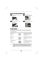
Front USB 3.0 Panel Installation Guide
 |
View all ASRock 890FX Deluxe5 manuals
Add to My Manuals
Save this manual to your list of manuals |
Page 32 highlights
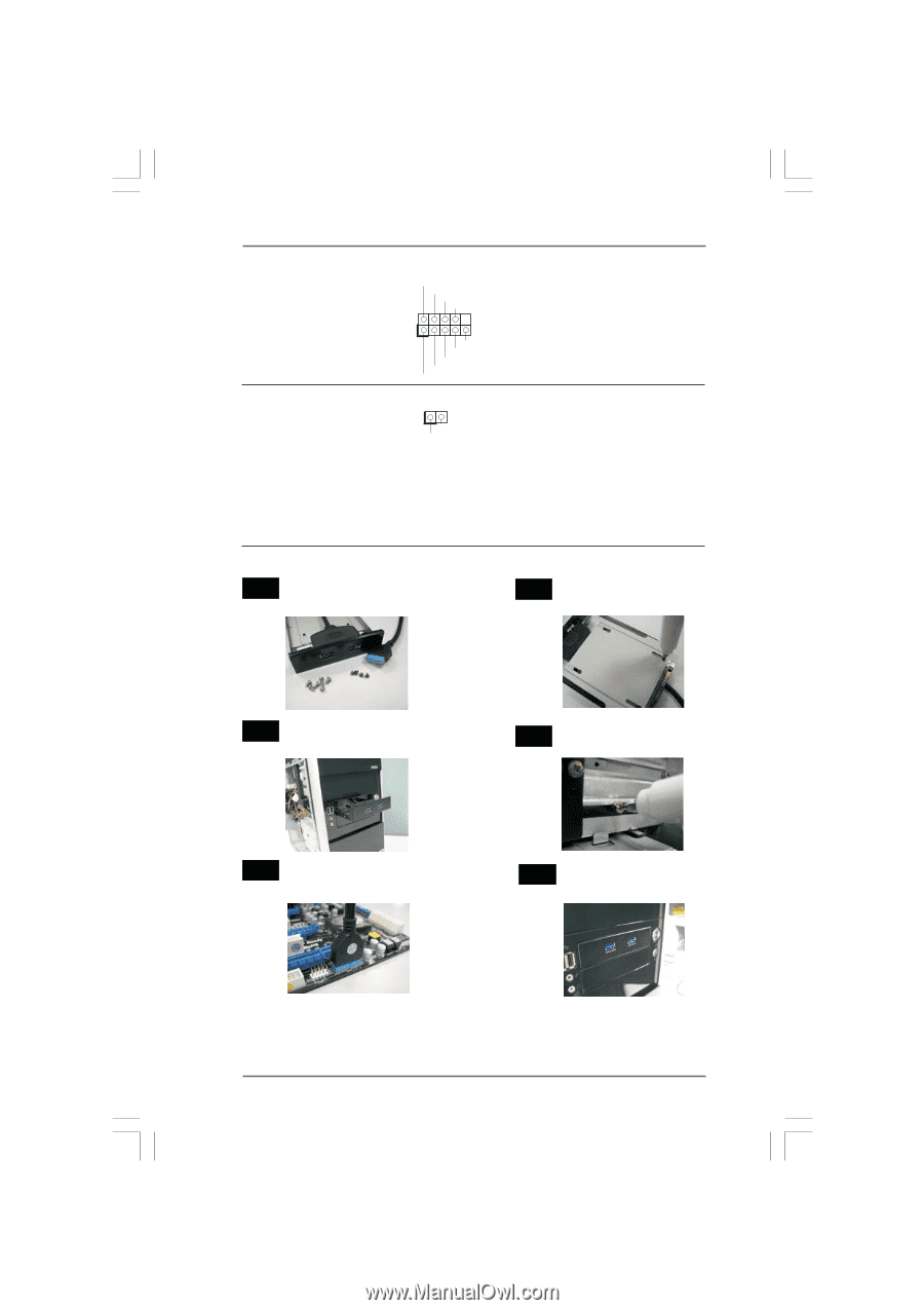
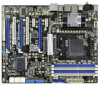
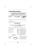
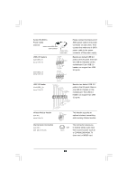
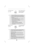
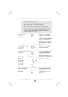
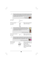
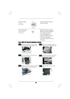
Serial port Header (9-pin COM1) (see p.12 No.30) HDMI_SPDIF Header (2-pin HDMI_SPDIF1) (see p.12 No. 45) RRXD1 DDTR#1 DDSR#1 CCTS#1 1 RRI#1 RRTS#1 GND TTXD1 DDCD#1 1 GND SPDIFOUT This COM1 header supports a serial port module. HDMI_SPDIF header, providing SPDIF audio output to HDMI VGA card, allows the system to con nect HDMI Digital TV/ projector/LCD devices. Please connect the HDMI_SPDIF connector of HDMI VGA card to this header. Front USB 3.0 Panel Installation Guide Step 1 Prepare the bundled Front USB 3.0 Panel, four HDD screws, and six chassis screws. Step 2 Screw the 2.5" HDD/SSD to the Front USB 3.0 Panel with four HDD screws. Step 3 Intall the Front USB 3.0 Panel into the 2.5" drive bay of the chassis. Step 4 Screw the Front USB 3.0 Panel to the drive bay with six chassis screws. Step 5 Plug the Front USB 3.0 cable into the USB 3.0 Step 6 The Front USB 3.0 Panel is ready header (USB3_1_2) on the motherboard. to use. 32
-
 1
1 -
2
-
3
-
4
-
5
-
6
-
7
-
8
-
9
-
10
-
11
-
12
-
13
-
14
-
15
-
16
-
17
-
18
-
19
-
20
-
21
-
22
-
23
-
24
-
25
-
26
-
 27
27 -
 28
28 -
 29
29 -
 30
30 -
 31
31 -
 32
32 -
 33
33 -
 34
34 -
 35
35 -
 36
36 -
 37
37 -
38
-
39
-
40
-
41
-
42
-
43
-
44
-
45
-
46
-
47
-
48
-
49
-
50
-
51
-
52
-
53
-
54
-
55
-
56
-
57
-
58
-
59
-
60
-
61
-
62
-
63
-
64
 |
 |