ASRock 960GM-VGS3 FX Quick Installation Guide - Page 8
English, 3 Pin Header Easy Installation Guide
 |
View all ASRock 960GM-VGS3 FX manuals
Add to My Manuals
Save this manual to your list of manuals |
Page 8 highlights
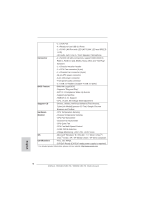
1.3 Pin Header Easy Installation Guide ASRock motherboard is equipped with pin headers with obvious colors which indicate you to recognize the crucial headers more easily. Please refer to below illustrations for the pin definition of onboard headers. If you want to have more information about the usage of these headers, please refer to "Jumpers Setup" and "Onboard Headers and Connectors" for details. GND PRESENCE# MIC_RET OUT_RET 1 OUT2_L J_SENSE OUT2_R MIC2_R MIC2_L Front Panel Audio Header USB_PWR PP+GND DUMMY 1 GND P+ PUSB_PWR USB 2.0 Header PLED+ PLEDPWRBTN# GND 1 DUMMY REST# GND HDLEDHDLED+ System Panel Header 8 ASRock 960GM-VGS3 FX / 960GM-VS3 FX Motherboard English
-
 1
1 -
2
-
 3
3 -
 4
4 -
 5
5 -
 6
6 -
 7
7 -
 8
8 -
 9
9 -
 10
10 -
 11
11 -
 12
12 -
 13
13 -
14
-
15
-
16
-
17
-
18
-
19
-
20
-
21
-
22
-
23
-
24
-
25
-
26
-
27
-
28
-
29
-
30
-
31
-
32
-
33
-
34
-
35
-
36
-
37
-
38
-
39
 |
 |

8
ASRock
960GM-VGS3 FX / 960GM-VS3 FX
Motherboard
English
1.3 Pin Header Easy Installation Guide
ASRock motherboard is equipped with pin headers with obvious colors which indi-
cate you to recognize the crucial headers more easily. Please refer to below illustra-
tions for the pin de
fi
nition of onboard headers. If you want to have more information
about the usage of these headers, please refer to “Jumpers Setup“ and “Onboard
Headers and Connectors“ for details.
1
GND
PRESENCE#
MIC_RET
MIC2_L
MIC2_R
OUT2_R
J_SENSE
OUT2_L
OUT_RET
Front Panel Audio Header
1
PLED+
PLED-
PWRBTN#
HDLED+
HDLED-
GND
REST#
GND
DUMMY
System Panel Header
USB 2.0 Header
1
USB_PWR
P-
P+
USB_PWR
P-
P+
GND
GND
DUMMY