ASRock 990FX Extreme9 User Guide - Page 44
Motherboard. Pro USB 3.0
 |
View all ASRock 990FX Extreme9 manuals
Add to My Manuals
Save this manual to your list of manuals |
Page 44 highlights
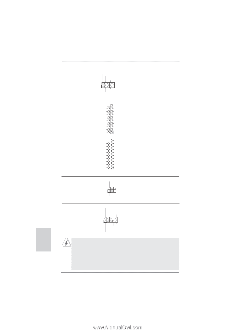
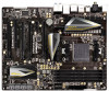
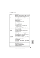
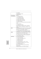
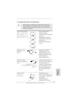
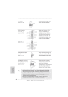
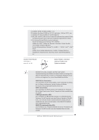
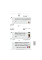
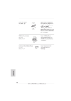
(9-pol. USB6_7) (siehe S.2 - No. 25) USB 3.0-Header (19-pol. USB3_4_5) (siehe S.2 - No. 12) (19-pol. USB3_6_7) (siehe S.2 - No. 11) USB_PWR P-7 P+7 GND DUMMY 1 GND P+6 P-6 USB PWR Anschlussleiste werden zwei USB 2.0-Ports unterstützt. Vbus IntA_P4_SSRXIntA_P4_SSRX+ GND IntA_P4_SSTXIntA_P4_SSTX+ GND IntA_P4_DIntA_P4_D+ Vbus IntA_P6_SSRXIntA_P6_SSRX+ GND IntA_P6_SSTXIntA_P6_SSTX+ GND IntA_P6_DIntA_P6_D+ Vbus IntA_P5_SSRXIntA_P5_SSRX+ GND IntA_P5_SSTXIntA_P5_SSTX+ GND IntA_P5_DIntA_P5_D+ ID 1 Vbus IntA_P7_SSRXIntA_P7_SSRX+ GND IntA_P7_SSTXIntA_P7_SSTX+ GND IntA_P7_DIntA_P7_D+ DUMMY Neben vier Standard-USB 3.0-Ports am E/A-Panel befinden sich zwei USB 3.0Anschlussleisten an diesem Motherboard. Pro USB 3.0Anschlussleiste werden zwei USB 3.0-Ports unterstützt. Infrarot-Modul-Header (5-pin IR1) (siehe S.2 - No. 32) IRTX +5VSB DUMMY 1 GND IRRX Dieser Header unterstützt ein optionales, drahtloses Sendeund Empfangs-Infrarotmodul. Anschluss für Audio auf der Gehäusevorderseite (9-Pin HD_AUDIO1) (siehe S.2 - No. 34) GND PRESENCE# MIC_RET OUT_RET 1 OUT2_L J_SENSE OUT2_R MIC2_R MIC2_L Dieses Interface zu einem Audio-Panel auf der Vorder seite Ihres Gehäuses, ermöglicht Ihnen eine bequeme Anschlussmöglichkeit und Kontrolle über Audio-Geräte. 1. High Definition Audio unterstützt Jack Sensing (automatische Erkennung falsch angeschlossener Geräte), wobei jedoch die Bildschirmverdrahtung am Gehäuse HDA unterstützen muss, um richtig zu funktionieren. Beachten Sie bei der Installation im System die Anweisungen in unserem Handbuch und im Gehäusehandbuch. 2. Wenn Sie die AC'97-Audioleiste verwenden, installieren Sie diese wie nachstehend beschrieben an der Front-Audioanschlussleiste: 44 ASRock 990FX Extreme9 Motherboard Deutsch
-
 1
1 -
2
-
3
-
4
-
5
-
6
-
7
-
8
-
9
-
10
-
11
-
12
-
13
-
14
-
15
-
16
-
17
-
18
-
19
-
20
-
21
-
22
-
23
-
24
-
25
-
26
-
27
-
28
-
29
-
30
-
31
-
32
-
33
-
34
-
35
-
36
-
37
-
38
-
 39
39 -
 40
40 -
 41
41 -
 42
42 -
 43
43 -
 44
44 -
 45
45 -
 46
46 -
 47
47 -
 48
48 -
 49
49 -
50
-
51
-
52
-
53
-
54
-
55
-
56
-
57
-
58
-
59
-
60
-
61
-
62
-
63
-
64
-
65
-
66
-
67
-
68
-
69
-
70
-
71
-
72
-
73
-
74
-
75
-
76
-
77
-
78
-
79
-
80
-
81
-
82
-
83
-
84
-
85
-
86
-
87
-
88
-
89
-
90
-
91
-
92
-
93
-
94
-
95
-
96
-
97
-
98
-
99
-
100
-
101
-
102
-
103
-
104
-
105
-
106
-
107
-
108
-
109
-
110
-
111
-
112
-
113
-
114
-
115
-
116
-
117
-
118
-
119
-
120
-
121
-
122
-
123
-
124
-
125
-
126
-
127
-
128
-
129
-
130
-
131
-
132
-
133
-
134
-
135
-
136
-
137
-
138
-
139
-
140
-
141
-
142
-
143
-
144
-
145
-
146
-
147
-
148
-
149
-
150
-
151
-
152
-
153
-
154
-
155
-
156
-
157
-
158
-
159
-
160
-
161
-
162
-
163
-
164
-
165
-
166
-
167
-
168
-
169
-
170
-
171
-
172
-
173
-
174
-
175
-
176
-
177
-
178
-
179
-
180
-
181
-
182
-
183
-
184
-
185
-
186
-
187
-
188
-
189
-
190
-
191
-
192
-
193
 |
 |