ASRock ALiveXFire-eSATA2 R3.0 User Manual
ASRock ALiveXFire-eSATA2 R3.0 Manual
 |
View all ASRock ALiveXFire-eSATA2 R3.0 manuals
Add to My Manuals
Save this manual to your list of manuals |
ASRock ALiveXFire-eSATA2 R3.0 manual content summary:
- ASRock ALiveXFire-eSATA2 R3.0 | User Manual - Page 1
ALiveXFire-eSATA2 User Manual Version 3.0 Published December 2007 Copyright©2006 ASRock INC. All rights reserved. 1 - ASRock ALiveXFire-eSATA2 R3.0 | User Manual - Page 2
purchaser for backup purpose, without written consent of ASRock Inc. Products and corporate names appearing in this manual may or may not be registered trademarks or copyrights USA ONLY The Lithium battery adopted on this motherboard contains Perchlorate, a toxic substance controlled in Perchlorate - ASRock ALiveXFire-eSATA2 R3.0 | User Manual - Page 3
Windows® VistaTM Premium 2007 and Basic Logo 9 1.4 Motherboard Layout 10 1.5 ASRock 6CH_eSATAII I/O 11 2 . Installation 12 Pre-installation Precautions 12 2.1 CPU Installation 13 2.2 Installation of CPU eSATAII Devices 36 2.15 Driver Installation Guide 36 2.16 Installing Windows® 2000 / XP / - ASRock ALiveXFire-eSATA2 R3.0 | User Manual - Page 4
43 3.1.1 BIOS Menu Bar 43 3.1.2 Navigation Keys 44 3.2 Main Screen 44 3.3 Advanced Screen 45 3.3.1 CPU Configuration 46 Software Support 60 4.1 Install Operating System 60 4.2 Support CD Information 60 4.2.1 Running Support CD 60 4.2.2 Drivers Menu 60 4.2.3 Utilities Menu 60 4.2.4 - ASRock ALiveXFire-eSATA2 R3.0 | User Manual - Page 5
guide to BIOS setup and information of the Support CD. Because the motherboard specifications and the BIOS software might be updated, the content of this manual will be subject to change without notice. In case any modifications of this manual occur, the updated version will be available on ASRock - ASRock ALiveXFire-eSATA2 R3.0 | User Manual - Page 6
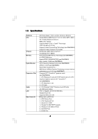
in, 30.5 cm x 20.8 cm - Socket AM2 for AMD PhenomTM X4 / X2, Athlon 64FX / 64X2 / X2 / 64 and Sempron processors - AMD LIVE!TM Ready - Supports AMD's Cool 'n' QuietTM Technology - FSB 1000 MHz (2.0 GT/s) - Supports Untied Overclocking Technology (see CAUTION 1) - Supports Hyper-Transport Technology - ASRock ALiveXFire-eSATA2 R3.0 | User Manual - Page 7
CAUTION 13) - 4Mb AMI BIOS - AMI Legal BIOS - Supports "Plug and Play" - ACPI 1.1 Compliance Wake Up Events - Supports jumperfree - SMBIOS 2.3.1 Support - Drivers, Utilities, AntiVirus Software (Trial Version) - CPU Temperature Sensing - Chassis Temperature Sensing - CPU Fan Tachometer - Chassis Fan - ASRock ALiveXFire-eSATA2 R3.0 | User Manual - Page 8
. To improve heat dissipation, remember to spray thermal grease between the CPU and the heatsink when you install the PC system. 7. This motherboard supports ASRock AM2 Boost overclocking technology. If you enable this function in the BIOS setup, the memory performance will improve up to 12.5%, but - ASRock ALiveXFire-eSATA2 R3.0 | User Manual - Page 9
2007 and Basic Logo For system integrators and users who purchase this motherboard and plan to submit Windows® VistaTM Premium 2007 and Basic logo, please follow below table for minimum hardware requirements. CPU Memory VGA Sempron 2800+ 1GB system memory (Premium) 512MB Single Channel (Basic - ASRock ALiveXFire-eSATA2 R3.0 | User Manual - Page 10
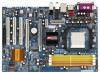
Motherboard Layout 123 4 56 PS2 Mouse 1 PS2_USB_PW1 ATX12V1 20.8cm (8.2-in) 78 Dual Core CPU PARALLEL PORT PS2 Keyboard DDRII_3 (64/72 bit, 240F-pSinBm8o0d0ule) DDRII_4 (64/72 bit, 240-pin module) DDRII_2 (64/72 bit, 240-pin module) DDRII_1 (64/72 bit, 240F-pSinBm8o0d0ule) SOCKET AM2 - ASRock ALiveXFire-eSATA2 R3.0 | User Manual - Page 11
1 . 5 ASRock 6CH_eSATAII I/O 1 2 5 3 6 4 7 12 11 10 9 8 1 Parallel Port 2 RJ-45 Port 3 Rear Speaker (Black) 4 Central header. Please refer to below steps for the software setting of Multi-Streaming. For Windows® XP: After restarting your computer, you will find "Mixer" tool on your - ASRock ALiveXFire-eSATA2 R3.0 | User Manual - Page 12
, peripherals, and/or components. 1. Unplug the power cord from the wall socket before touching any component. 2. To avoid damaging the motherboard components due to static electricity, NEVER place your motherboard directly on the carpet or the like. Also remember to use a grounded wrist strap - ASRock ALiveXFire-eSATA2 R3.0 | User Manual - Page 13
Corner Small Triangle STEP 2 / STEP 3: Match The CPU Golden Triangle To The Socket Corner Small Triangle STEP 4: Push Down And Lock The Socket Lever 2.2 Installation of CPU Fan and Heatsink After you install the CPU into this motherboard, it is necessary to install a larger heatsink and cooling - ASRock ALiveXFire-eSATA2 R3.0 | User Manual - Page 14
2.3 Installation of Memory Modules (DIMM) This motherboard provides four 240-pin DDR2 (Double Data Rate 2) DIMM slots, and supports Dual Channel Memory Technology. For dual channel configuration, you always need to install identical (the same brand, speed, size and chip-type) DDR2 DIMM pair - ASRock ALiveXFire-eSATA2 R3.0 | User Manual - Page 15
matches the break on the slot. notch break notch break The DIMM only fits in one correct orientation. It will cause permanent damage to the motherboard and the DIMM if you force the DIMM into the slot at incorrect orientation. Step 3. Firmly insert the DIMM into the slot until the retaining - ASRock ALiveXFire-eSATA2 R3.0 | User Manual - Page 16
2.4 Expansion Slots (PCI and PCI Express Slots) There are 3 PCI slots and 3 PCI Express slots on this motherboard. PCI slots: PCI slots are used to install expansion cards that have the 32-bit PCI interface. PCIE Slots: PCIE1 slot (PCI Express x1 slot) - ASRock ALiveXFire-eSATA2 R3.0 | User Manual - Page 17
the expansion card and make necessary hardware settings for the card before you start the installation. Step 2. Remove the system unit cover (if your motherboard is already installed in a chassis). Step 3. Remove the bracket facing the slot that you intend to use. Keep the screws for later use. Step - ASRock ALiveXFire-eSATA2 R3.0 | User Manual - Page 18
2.5 Installing a Single Graphics Card Step 1. Install a PCI Express x16 graphics card on PCIE3 slot. Please refer to page 17 for proper procedures of installing an expansion card. Step 2. Make sure that the PCIE Switch card is installed on PCIE2/PCIE SWITCH slot to avail of the PCI Express x16 - ASRock ALiveXFire-eSATA2 R3.0 | User Manual - Page 19
supported with Windows® XP with Service Pack 2. Please check ATITM website for driver updates. What graphics cards work with CrossFireTM? w A complete CrossFireTM system requires a CrossFireTM Ready motherboard future, please refer to ATITM graphics card manuals for detailed installation guide. 19 - ASRock ALiveXFire-eSATA2 R3.0 | User Manual - Page 20
connect a hard disk power connector to SLI/XFIRE Power connector on this motherboard. It is recommended to use 500-Watt power supply or greater to from the same series on PCIE2/PCIE SWITCH slot and PCIE3 slot to support CrossFireTM. Besides, please connect the monitor cable to the graphics card on - ASRock ALiveXFire-eSATA2 R3.0 | User Manual - Page 21
graphics card and one compatible standard Radeon (CrossFireTM Ready) graphics card to this motherboard, please connect one end of DVI-DMS cable to the monitor, another end Catalyst drivers prior to installation. Please visit this website for the driver: http://support.ati.com/ics/support/DLRedirect. - ASRock ALiveXFire-eSATA2 R3.0 | User Manual - Page 22
to your system. Please visit the websites below for installing the drivers that ATITM recommends: A. ATITM recommends Windows® XP Service Pack 2 or higher to be installed (If you have Windows® XP Service Pack 2 or higher installed in your system, there is no need to download it again): http://www - ASRock ALiveXFire-eSATA2 R3.0 | User Manual - Page 23
If you install one Radeon CrossFireTM Edition graphics card and one compatible standard Radeon (CrossFireTM Ready) graphics card to this motherboard but not two Radeon CrossFireTM Edition graphics cards, please as well follow the above steps. However, although you have selected the option "Enable - ASRock ALiveXFire-eSATA2 R3.0 | User Manual - Page 24
Display Feature This motherboard supports Surround Display upgrade. With the external add-on ATI PCI Express VGA cards, you can easily enjoy the benefits of Surround Display feature. For the detailed instruction, please refer to the document at the following path in the Support CD: ..\ Surround - ASRock ALiveXFire-eSATA2 R3.0 | User Manual - Page 25
blue end to the motherboard connect the black end to the IDE devices 80-conductor ATA 66/100/133 cable Note: Please refer to the instruction of your IDE device , No. 36) eSATAII_TOP eSATAII_BOTTOM These two eSATAII connectors support SATA data cables for external SATAII function. The current - ASRock ALiveXFire-eSATA2 R3.0 | User Manual - Page 26
P-7 P+7 GND DUMMY 1 GND P+6 P-6 USB_PWR Besides two default USB 2.0 ports on the I/O panel, there are four USB 2.0 headers on this motherboard. Each USB 2.0 header can support two USB 2.0 ports. (9-pin USB4_5) (see p.10 No. 18) (9-pin USB2_3) (see p.10 No. 17) USB_PWR P-5 P+5 GND DUMMY 1 GND - ASRock ALiveXFire-eSATA2 R3.0 | User Manual - Page 27
allows convenient connection and control of audio devices. 1. High Definition Audio supports Jack Sensing, but the panel wire on the chassis must support HDA to function correctly. Please follow the instruction in our manual and chassis manual to install your system. 2. If you use AC'97 audio - ASRock ALiveXFire-eSATA2 R3.0 | User Manual - Page 28
to the ground pin. Though this motherboard provides 4-Pin CPU fan (Quiet Fan) support, the 3-Pin CPU fan still can work successfully even without the fan speed control function. If you plan to connect the 3-Pin CPU fan to the CPU fan connector on this motherboard, please connect it to Pin 1-3. Pin - ASRock ALiveXFire-eSATA2 R3.0 | User Manual - Page 29
connect the black end (A) of HDMI_SPDIF cable to the HDMI_SPDIF header on the motherboard. Then connect the white end (B or C) of HDMI_SPDIF cable to the C. white end (3-pin) SPDIFOUT GND blue black This USB bracket can support 2 additional USB 2.0 ports besides the I/O panel. Please connect the - ASRock ALiveXFire-eSATA2 R3.0 | User Manual - Page 30
motherboard with a HDMI_SPDIF header. This motherboard motherboard, please carefully follow motherboard. For the proper installation of HDMI VGA card, please refer to the installation guide motherboard. Make sure to correctly connect the HDMI_SPDIF cable to the motherboard the motherboard user manual for - ASRock ALiveXFire-eSATA2 R3.0 | User Manual - Page 31
If you set "SATA Operation Mode" option in BIOS setup to non-RAID mode, Hot Plug function is not supported with eSATAII devices. If you still want to eSATAII_BOTTOM 1. If you just plan to install one eSATAII device to this motherboard, it is recommended to enable the bottom eSATAII port of the I/O - ASRock ALiveXFire-eSATA2 R3.0 | User Manual - Page 32
connector (SATAII_RED (PORT 1)) Connect the SATA data cable to the red eSATAII connector (eSATAII_BOTTOM) 2. If you plan to install two eSATAII devices to this motherboard, you need to enable both the top and the bottom eSATAII ports of the I/O shield. In order to enable the top and the bottom - ASRock ALiveXFire-eSATA2 R3.0 | User Manual - Page 33
3. Use the eSATAII device cable to connect eSATAII device and the eSATAII port of the I/O shield according to the eSATAII connector that you connect the SATA data cable. Connect one end of the eSATAII device cable to eSATAII device Connect the other end of the eSATAII device cable to eSATAII port - ASRock ALiveXFire-eSATA2 R3.0 | User Manual - Page 34
guide. Some default setting of SATAII hard disks may not be at SATAII mode, which operate with the best performance. In order to enable SATAII function, please follow the below instruction 's website for details: http://www.hitachigst.com/hdd/support/download.htm The above examples are just for your - ASRock ALiveXFire-eSATA2 R3.0 | User Manual - Page 35
ATITM SB600 south bridge chipset that supports Serial ATA (SATA) / Serial ATAII (SATAII) hard disks and RAID (RAID 0, RAID 1, and RAID 10) functions. You may install SATA / SATAII hard disks on this motherboard for internal storage devices. This section will guide you to install the SATA / SATAII - ASRock ALiveXFire-eSATA2 R3.0 | User Manual - Page 36
to the eSATAII ports instead of opening your chassis to exchange your SATAII hard disk. 2.15 Driver Installation Guide To install the drivers to your system, please insert the support CD to your optical drive first. Then, the drivers compatible to your system can be auto-detected and listed on the - ASRock ALiveXFire-eSATA2 R3.0 | User Manual - Page 37
Mode" option to [RAID]. STEP 2: Make a SATA / SATAII Driver Diskette. A. Insert the ASRock Support CD into your optical drive to boot your system. B. During POST at the beginning of system boot-up, press key, and then a window for boot devices selection appears. Please select CD- ROM as - ASRock ALiveXFire-eSATA2 R3.0 | User Manual - Page 38
you need to check the RAID installation guide in the Support CD for proper configuration. Please refer to the BIOS RAID installation guide part of the document in the following path in the Support CD: .. \ RAID Installation Guide STEP 4: Install Windows® 2000 / Windows® XP / Windows® XP 64-bit OS on - ASRock ALiveXFire-eSATA2 R3.0 | User Manual - Page 39
you want to install Windows?" page, please insert the ASRock Support CD into your optical drive, and click the "Load Driver" button on the left on the bottom to load the ATITM RAID drivers. ATITM RAID drivers are in the following path in our Support CD: .. \ I386 (For Windows® VistaTM OS) .. \ AMD64 - ASRock ALiveXFire-eSATA2 R3.0 | User Manual - Page 40
proper operating procedures of creating JBOD, please refer to the BIOS RAID installation guide part of the document in the following path in the Support CD: .. \ RAID Installation Guide 1. JBOD function on this motherboard is only supported with single SATA / SATAII HDD. 2. If you want to enable - ASRock ALiveXFire-eSATA2 R3.0 | User Manual - Page 41
to boot your system, and follow the instruction to install Windows® VistaTM / Windows® VistaTM 64-bit OS on your system. When you see "Where do you want to install Windows?" page, please insert the ASRock Support CD into your optical drive, and click the "Load Driver" button on the left on the - ASRock ALiveXFire-eSATA2 R3.0 | User Manual - Page 42
This motherboard supports Untied Overclocking Technology, which means during overclocking, FSB enjoys better margin due to fixed PCI / PCIE buses. Before you enable Untied Overclocking function, please enter "Overclock Mode" option of BIOS setup to set the selection from [Auto] to [Manual]. Then - ASRock ALiveXFire-eSATA2 R3.0 | User Manual - Page 43
the BIOS SETUP UTILITY to configure your system. The Flash Memory on the motherboard stores the BIOS SETUP UTILITY. You may run the BIOS SETUP off and then back on. Because the BIOS software is constantly being updated, the following BIOS setup screens and descriptions are for reference purpose - ASRock ALiveXFire-eSATA2 R3.0 | User Manual - Page 44
System Time System Date [17:00:09] [Fri 08/25/2006] BIOS Version : ALiveXFire-eSATA2 BIOS P1.0 Processor Type : AMD Athlon(tm) 64 X2 Dual Core Processor 4200+ (64bit supported) Processor Speed : 2200 MHz Microcode Update : 40FB2/0 Cache Size : 1024KB Total Memory DDRII1 DDRII2 DDRII3 DDRII4 - ASRock ALiveXFire-eSATA2 R3.0 | User Manual - Page 45
Megatrends, Inc. Setting wrong values in this section may cause the system to malfunction. 3.3.1 CPU Configuration BIOS SETUP UTILITY Advanced CPU Configuration AM2 Boost Overclock Mode CPU Frequency (MHz) PCIE Frequency (MHz) Spread Spectrum Boot Failure Guard Cool' n' Quiet Processor Maximum - ASRock ALiveXFire-eSATA2 R3.0 | User Manual - Page 46
install Windows® Support This item will show if you use Dual Core CPU Manual], you may adjust the value of Processor Multiplier and Processor Voltage. However, it is recommended to keep the default value for system stability. BIOS SETUP UTILITY Advanced CPU Configuration AM2 Boost Overclock Mode CPU - ASRock ALiveXFire-eSATA2 R3.0 | User Manual - Page 47
item will show when "Multiplier/Voltage Change" is set to [Manual]; otherwise, it will be hidden. You may set the this item. Processor Voltage This item will show when "Multiplier/Voltage Change" is set to [Manual]; otherwise, it will be hidden. You may set the value from [1.550V] down to [0.800V - ASRock ALiveXFire-eSATA2 R3.0 | User Manual - Page 48
access contention. 3.3.2 Chipset Configuration BIOS SETUP UTILITY Advanced Chipset Settings Onboard CPU-NB Link Width [Auto] [Auto] DRAM Voltage NB Core Voltage NB +1.8V Voltage PCI Bridge Decode Scheme [Auto] [Auto] [Auto] [Auto] DRAM Voltage 2.0V and 2.05V options are for overclocking - ASRock ALiveXFire-eSATA2 R3.0 | User Manual - Page 49
options: [Auto], [1.85V], [1.9V], [1.95V], [2.0V], and [2.05V]. The default value is [Auto]. DRAM Voltage 2.0V and 2.05V options are for overclocking usage only, which may violate memory specification. NB Core Voltage Use this to select NB core voltage. Configuration options: [Auto], [Ultra High - ASRock ALiveXFire-eSATA2 R3.0 | User Manual - Page 50
3.3.3 ACPI Configuration BIOS SETUP UTILITY Advanced ACPI Settings Suspend To RAM Repost Video on STR Resume Away Mode Support Restore on AC resume. (STR refers to suspend to RAM.) Away Mode Support Use this item to enable or disable Away Mode support under Windows® XP Media Center OS. The default - ASRock ALiveXFire-eSATA2 R3.0 | User Manual - Page 51
plan to use this motherboard to submit Windows® VistaTM certification. 3.3.4 IDE Configuration Advanced BIOS SETUP UTILITY IDE as the example in the following instruction, which can be applied to the configurations of "Primary IDE Slave" as well. BIOS SETUP UTILITY Advanced IDE Master Device - ASRock ALiveXFire-eSATA2 R3.0 | User Manual - Page 52
automatically detect the hard disk drive. After selecting the hard disk information into BIOS, use a disk utility, such as FDISK, to partition and format the item to select the LBA/Large mode for a hard disk > 512 MB under DOS and Windows; for Netware and UNIX user, select [Disabled] to disable the - ASRock ALiveXFire-eSATA2 R3.0 | User Manual - Page 53
PCI IDE BusMaster feature. 3.3.6 Floppy Configuration In this section, you may configure the type of your floppy drive. BIOS SETUP UTILITY Advanced Floppy Configuration Floppy A [1.44 MB 312"] Select the type of floppy drive connected to the system. +F1 F9 F10 ESC Select Screen Select Item - ASRock ALiveXFire-eSATA2 R3.0 | User Manual - Page 54
Address Parallel Port Mode EPP Version ECP Mode DMA Channel Parallel Port IRQ [Enabled] [3F8 / IRQ4] [Disabled] [378] [ECP + EPP] [1.9] [DMA3] [IRQ7] Allow BIOS to Enable or Disable Floppy Controller. +F1 F9 F10 ESC Select Screen Select Item Change Option General Help Load Defaults Save and Exit - ASRock ALiveXFire-eSATA2 R3.0 | User Manual - Page 55
3.3.8USB Configuration BIOS SETUP UTILITY Advanced USB Configuration USB Controller USB 2.0 Support Legacy USB Support [Enabled] [Enabled] [Disabled] To enable or disable the onboard USB controllers. +F1 F9 F10 ESC Select Screen Select Item Change Option General Help Load Defaults - ASRock ALiveXFire-eSATA2 R3.0 | User Manual - Page 56
you to monitor the status of the hardware on your system, including the parameters of the CPU temperature, motherboard temperature, CPU fan speed, chassis fan speed, and the critical voltage. BIOS SETUP UTILITY Main Advanced H/W Monitor Boot Security Exit Hardware Health Event Monitoring - ASRock ALiveXFire-eSATA2 R3.0 | User Manual - Page 57
General Help F9 Load Defaults F10 Save and Exit ESC Exit v02.54 (C) Copyright 1985-2003, American Megatrends, Inc. 3.5.1 Boot Settings Configuration BIOS SETUP UTILITY Boot Boot Settings Configuration Boot From Network Bootup Num-Lock [Disabled] [On] To enable or disable the boot from network - ASRock ALiveXFire-eSATA2 R3.0 | User Manual - Page 58
you may set or change the supervisor/user password for the system. For the user password, you may also clear it. BIOS SETUP UTILITY Main Advanced H/W Monitor Boot Security Exit Security Settings Supervisor Password : Not Installed User Password : Not Installed Change Supervisor Password - ASRock ALiveXFire-eSATA2 R3.0 | User Manual - Page 59
and exit setup?" Select [OK] to save the changes and exit the BIOS SETUP UTILITY. Discard Changes and Exit When you select this option, it message, "Discard changes and exit setup?" Select [OK] to exit the BIOS SETUP UTILITY without saving any changes. Discard Changes When you select this option - ASRock ALiveXFire-eSATA2 R3.0 | User Manual - Page 60
to your OS documentation for more information. 4.2 Support CD Information The Support CD that came with the motherboard contains necessary drivers and useful utilities that enhance the motherboard features. 4.2.1 Running The Support CD To begin using the support CD, insert the CD into your CD-ROM
-
 1
1 -
 2
2 -
 3
3 -
 4
4 -
 5
5 -
 6
6 -
 7
7 -
8
-
9
-
10
-
11
-
12
-
13
-
14
-
15
-
16
-
17
-
18
-
19
-
20
-
21
-
22
-
23
-
24
-
25
-
26
-
27
-
28
-
29
-
30
-
31
-
32
-
33
-
34
-
35
-
36
-
37
-
38
-
39
-
40
-
41
-
42
-
43
-
44
-
45
-
46
-
47
-
48
-
49
-
50
-
51
-
52
-
53
-
54
-
55
-
56
-
57
-
58
-
59
-
60
 |
 |

1
ALiveXFire-eSATA2
User Manual
Version 3.0
Published December 2007
Copyright©2006 ASRock INC. All rights reserved.