ASRock B75TM-ITX User Manual - Page 33
W Audio AMP Output
 |
View all ASRock B75TM-ITX manuals
Add to My Manuals
Save this manual to your list of manuals |
Page 33 highlights
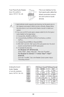
3W Audio AMP Output Wafer Header (4-pin SPEAKER1) (see p.13/15/17, No. 28) Front_RFront_R+ Front_L+ Front_L1 Please connect the chassis speaker to this header. Power LED Header (3-pin PLED1) (see p.13/15/17, No. 11) PLEDPLED+ PLED+ 1 Please connect the chassis power LED to this header to indicate system power status. The LED is on when the system is operating. The LED keeps blinking in S1/S3 state. The LED is off in S4 state or S5 state (power off). Chassis Fan Connector (4-pin CHA_FAN1) (see p.13/15/17, No. 4) FAN_SPEED_CONTROL FAN_SPEED +12V GND 1 234 Please connect a fan cable to the fan connector and match the black wire to the ground pin. CPU Fan Connectors (4-pin CPU_FAN1) (see p.13/15/17, No. 22) FAN_SPEED_CONTROL FAN_SPEED +12V GND 4 Though this motherboard 3 2 1 provides a 4-Pin CPU fan (Quiet Fan) connector, 3-Pin CPU fans can still work even without fan speed control. If you plan to connect a 3-Pin CPU fan, please connect it to Pin 1-3. Serial Port Header (10-pin COM1) (see p.13/15/17, No. 18) COM PWR/DCD RXD TXD DTR GND 1 DSR RTS CTS COM PWR/RI NC This COM1 header supports a serial port module. 33
-
 1
1 -
2
-
3
-
4
-
5
-
6
-
7
-
8
-
9
-
10
-
11
-
12
-
13
-
14
-
15
-
16
-
17
-
18
-
19
-
20
-
21
-
22
-
23
-
24
-
25
-
26
-
27
-
 28
28 -
 29
29 -
 30
30 -
 31
31 -
 32
32 -
 33
33 -
 34
34 -
 35
35 -
 36
36 -
 37
37 -
 38
38 -
39
-
40
-
41
-
42
-
43
-
44
-
45
-
46
-
47
-
48
-
49
-
50
-
51
-
52
-
53
-
54
-
55
-
56
-
57
-
58
-
59
-
60
-
61
-
62
-
63
-
64
-
65
-
66
-
67
 |
 |
