ASRock C216 WS User Manual
ASRock C216 WS Manual
 |
View all ASRock C216 WS manuals
Add to My Manuals
Save this manual to your list of manuals |
ASRock C216 WS manual content summary:
- ASRock C216 WS | User Manual - Page 1
C216 WS User Manual Version 1.0 Published December 2012 Copyright©2012 ASRock INC. All rights reserved. 1 - ASRock C216 WS | User Manual - Page 2
any form or by any means, except duplication of documentation by the purchaser for backup purpose, without written consent of ASRock Inc. Products and corporate names appearing in this manual may or may not be registered trademarks or copyrights of their respective companies, and are used only for - ASRock C216 WS | User Manual - Page 3
Contents 1 Introduction 5 1.1 Package Contents 5 1.2 Specifications 6 1.3 Unique Features 10 1.4 Motherboard Layout 11 1.5 Onboard Headers and Connectors 32 2.11 Dr. Debug 37 2.12 Teaming Function Operation Guide 38 3 UEFI SETUP UTILITY 42 3.1 Introduction 42 3.1.1 UEFI Menu Bar 42 3.1.2 - ASRock C216 WS | User Manual - Page 4
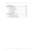
Operating System 66 4.2 Support CD Information 66 4.2.1 Running Support CD 66 4.2.2 Drivers Menu 66 4.2.3 Utilities Menu 66 4.2.4 Contact Information 66 5 Troubleshooting 67 5.1 Troubleshooting Procedures 67 5.2 Technical Support Procedures 69 5.3 Returning Merchandise for Service 69 4 - ASRock C216 WS | User Manual - Page 5
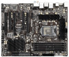
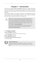
specific information about the model you are using. www.asrock.com/support/index.asp 1.1 Package Contents ASRock C216 WS Motherboard (ATX Form Factor: 12.0-in x 9.6-in, 30.5 cm x 24.4 cm) ASRock C216 WS User Manual ASRock C216 WS Support CD 6 x Serial ATA (SATA) Data Cables (Optional) 1 x I/O Panel - ASRock C216 WS | User Manual - Page 6
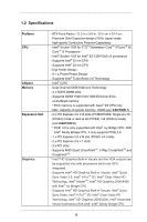
CoreTM i7/CoreTM i5/ CoreTM i3 Processors - Intel® Socket 1155 for Intel® E3-1200/12x5 v2 processors - Supports Intel® 32 nm CPU - Supports Intel® 22 nm CPU - Digi Power Design - 8 + 4 Power Phase Design - Supports Intel® Turbo Boost 2.0 Technology - Intel® C216 - Dual Channel DDR3 Memory Technology - ASRock C216 WS | User Manual - Page 7
and "Hot Plug" functions (SATA3_A4 connector is shared with eSATA3 port) - 4 x SATA2 3.0 Gb/s connectors by Intel® C216, support RAID (RAID 0, RAID 1, RAID 5, RAID 10, Intel Rapid Storage and Intel Smart Response Technology), NCQ, AHCI and Hot Plug functions I/O Panel - 1 x PS/2 Keyboard/Mouse Port - ASRock C216 WS | User Manual - Page 8
Intel® C216, support USB 1.1/2.0/3.0 up to 5Gb/s - 4 x Rear USB 3.0 ports by Etron EJ188H, support USB 1.1/2.0/3.0 up to 5Gb/s - 1 x Front USB 3.0 header by Intel® C216 (supports 2 USB 3.0 ports), supports 2.3.1 Support - CPU Core, IGPU, DRAM, 1.8V PLL, VTT, VCCSA Voltage Multi-adjustment - Drivers, - ASRock C216 WS | User Manual - Page 9
For detailed product information, please visit our website: http://www.asrock.com WARNING Please realize that there is a certain risk involved with 64-bit CPU, there is no such limitation. 2. Only PCIE2 and PCIE4 slots support Gen 3 speed. To run the PCI Express in Gen 3 speed, please install an - ASRock C216 WS | User Manual - Page 10
ASRock Instant Flash ASRock to enter into the BIOS setup menu to access ASRock Instant Flash. Just launch this tool and save the FAT32/16/12 file system. ASRock Crashless BIOS ASRock Crashless BIOS allows users to during the BIOS update process, ASRock Crashless BIOS will automatically finish the - ASRock C216 WS | User Manual - Page 11
1 HDMI_SPDIF1 COM1 1 1 PCI2 C216 WS PCIE5 IR1 1 FRONT_1394 1 CLRCMOS1 1 CHA_FAN1 USB8_9 1 USB6_7 1 Dr. Debug 64Mb BIOS SPEAKER1 1 PLED1 1 PLED PWRBTN CHA_FAN3 1 HDLED RESET PANEL1 15 27 26 25 24 23 22 21 20 19 18 17 16 1 1155-Pin CPU Socket 2 ATX 12V Power Connector (ATX12V1 - ASRock C216 WS | User Manual - Page 12
1.5 I/O Panel 1 2 34 58 69 7 10 17 16 15 14 13 12 11 1 PS/2 Keyboard/Mouse Port (Purple/Green) 10 Microphone (Pink) * 2 LAN RJ-45 Port 11 USB 3.0 Ports (USB3_45) 3 USB 2.0 Ports (USB45) 12 IEEE 1394 Port * 4 LAN RJ-45 Port *** 13 eSATA3 Port (ESATA_1) 5 Central / Bass (Orange) 14 - ASRock C216 WS | User Manual - Page 13
Primary output" to use Rear Speaker, Central/Bass, and Front Speaker, or select "Realtek HDA Audio 2nd output" to use front panel audio. *** eSATA3 connector supports SATA Gen3 in cable 1M. 13 - ASRock C216 WS | User Manual - Page 14
!Qjo!Tpdlfu ENJ GEJ!MJOL 3!Gspou!VTC4!qpsut 3!sfbs!VTC4!qpsut Ijhi.Tqffe!VTC 9!qpsut Sfbmufl!BMD9:3 QDJ.F!Y5 591Nc0t 24MHz PCIE x4 100MHz Intel C216 Panther Point PCH SPI FLASH 64Mb SPI IENJ!Dpoofdups Etron EJ188 DIGITAL PORT D QDJF!y2 100MHz 5!sfbs!VTC4!qpsut 239.cju!Evbm.Diboofm!Nfnpsz - ASRock C216 WS | User Manual - Page 15
Chapter 2: Installation This is an ATX form factor (12.0" x 9.6", 30.5 x 24.4 cm) motherboard. Before you install the components or change any motherboard settings. 1. Unplug the power cord from the wall socket before touching any components. 2. To avoid damaging the motherboard's components due to - ASRock C216 WS | User Manual - Page 16
In order to provide the LGA 1155 CPU sockets more protection and make the installation process easier, ASRock has added a new protection cover on top of the load plate to replace the former PnP caps that were under the load plate. For the installation of Intel® 1155-Pin CPUs with the new protection - ASRock C216 WS | User Manual - Page 17
1155-Pin CPU alignment key 1155-Pin Socket Pin1 For proper installation, please ensure to match the two orientation key notches of the CPU with the two alignment keys of the socket. Step 2-3. Carefully place the CPU into the socket if you wish to return the motherboard for after service. 17 - ASRock C216 WS | User Manual - Page 18
with 1155-Pin socket that supports Intel 1155-Pin CPUs. Please adopt the type of heatsink and cooling fan compliant with Intel 1155Pin kindly refer to the instruction manuals of your CPU fan and heatsink. Below is an example to illustrate the installation of the heatsink for 1155-Pin CPUs. Step 1. - ASRock C216 WS | User Manual - Page 19
2.5 Installation of Memory Modules (DIMM) This motherboard provides four 240-pin DDR3 (Double Data Rate 3) DIMM slots, and supports Dual Channel Memory Technology. For dual channel configuration, you always need to install identical (the same brand, speed, size and chip-type) DDR3 DIMM pair - ASRock C216 WS | User Manual - Page 20
Installing a DIMM Please make sure to disconnect power supply before adding or removing DIMMs or the system components. Step 1. Step 2. Unlock a DIMM slot by pressing the retaining clips outward. Align a DIMM on the slot such that the notch on the DIMM matches the break on the slot. notch - ASRock C216 WS | User Manual - Page 21
PCI Express x1 lane width card, such as a Gigabit LAN card, SATA2 card or ASRock Game Blaster, etc. PCIE3 (PCIE 2.0 x1 slot) is used for a PCI Express x16 lane width graphics cards, or to install PCI Express graphics cards to support CrossFireXTM function. PCIE4 (PCIE 3.0 x16 slot) is used for PCI - ASRock C216 WS | User Manual - Page 22
Installing an expansion card Step 1. Before installing an expansion card, please make sure that the power supply is switched off or the power cord is unplugged. Please read the documentation of the expansion card and make necessary hardware settings for the card before you start the installation. - ASRock C216 WS | User Manual - Page 23
CrossFireXTM Operation Guide This motherboard supports CrossFireXTM, Please check AMD website for ATITM CrossFireXTM driver updates. 1. If a customer incorrectly configures the future, please refer to AMD graphics card manuals for detailed installation guide. Step 1. Insert one Radeon graphics card - ASRock C216 WS | User Manual - Page 24
Step 2. Connect two Radeon graphics cards by installing CrossFire Bridge on CrossFire Bridge Interconnects on the top of Radeon graphics cards. (CrossFire Bridge is provided with the graphics card you purchase, not bundled with this motherboard. Please refer to your graphics card vendor for details - ASRock C216 WS | User Manual - Page 25
2.7.1.2 Installing Three CrossFireXTM-Ready Graphics Cards Step 1. Install the identical 3-Way CrossFireXTM-ready graphics cards that are AMD certified because different types of graphics cards will not work together properly. (Even the GPU chips version shall be the same.) Insert one graphics card - ASRock C216 WS | User Manual - Page 26
system. For Windows® 8 / 7 OS: Install the CATALYST Control Center. Please check AMD website for details. Restart your computer. Install the VGA card drivers to your system, and restart your computer. Then you will find "ATI Catalyst Control Center" on your Windows® taskbar. ATI Catalyst Control - ASRock C216 WS | User Manual - Page 27
Although you have selected the option "Enable CrossFireTM", the CrossFireXTM function may not work actually. Your computer will automatically reboot. After restarting your computer, please confirm whether the option "Enable CrossFireTM" in "ATI Catalyst Control Center" is selected or not; - ASRock C216 WS | User Manual - Page 28
display upgrade. With the internal VGA output support (HDMI port) and external add-on PCI inserted to this motherboard. 4. Install the onboard VGA driver and the add-on PCI Express VGA card driver to your system. If you have installed the drivers already, there is no need to install them again. - ASRock C216 WS | User Manual - Page 29
For Windows® 8 / 8 64-bit / 7 / 7 64-bit OS: Right click the desktop, choose "Personalize", and select the "Display Settings" tab so that you can adjust the parameters of the multi-monitors according to the steps below. A. Click the number "2" icon. B. Click the items "This is my main monitor" and " - ASRock C216 WS | User Manual - Page 30
HDCP function with this motherboard, you need to adopt a monitor that supports HDCP function as well. Therefore, you can enjoy the superior display quality with high-definition HDCP encryption contents. Please refer to the instructions below for more details about HDCP function. What is HDCP? HDCP - ASRock C216 WS | User Manual - Page 31
first, and then shut it down before you do the clear-CMOS action. Please be noted that the password, date, time, user default profile, 1394 GUID and MAC address will be cleared only if the CMOS battery is removed. 31 - ASRock C216 WS | User Manual - Page 32
11, No. 12) SATA3_A3 (SATA3_A1_A2: see p.11, No. 11) (SATA3_A3_A4: see p.11, No. 10) SATA3_A1 SATA3_0 These six Serial ATA3 (SATA3) SATA3_A4 connectors support SATA data cables for internal storage devices. The current SATA3 SATA3_A2 interface allows up to 6.0 Gb/s data transfer rate. If the eSATA3 - ASRock C216 WS | User Manual - Page 33
allows convenient connection and control of audio devices. 1. High Definition Audio supports Jack Sensing, but the panel wire on the chassis must support HDA to function correctly. Please follow the instruction in our manual and chassis manual to install your system. 2. If you use AC'97 audio panel - ASRock C216 WS | User Manual - Page 34
System Panel Header (9-pin PANEL1) (see p.11, No. 18) This header accommodates several system front panel functions. Connect the power switch, reset switch and system status indicator on the chassis to this header according to the pin assignments below. Note the positive and negative pins before - ASRock C216 WS | User Manual - Page 35
motherboard provides 4-Pin CPU fan (Quiet Fan) support, the 3-Pin CPU fan still can work ATX power supply to this connector. 1 13 Though this motherboard provides 24-pin ATX power connector, 12 24 it can still work if you adopt a traditional 20-pin ATX power supply. To use the 20-pin ATX - ASRock C216 WS | User Manual - Page 36
8 5 IEEE 1394 Header (9-pin FRONT_1394) (see p.11 No. 24) 4-Pin ATX 12V Power Supply Installation 4 1 RXTPAM_0 GND RXTPBM_0 +12V GND 1 +12V RXTPBP_0 GND (9-pin COM1) (see p.11, No. 26) This COM1 header supports a serial port module. HDMI_SPDIF Header (2-pin HDMI_SPDIF1) (see p.11, - ASRock C216 WS | User Manual - Page 37
Dr. Debug is used to provide code information, which makes troubleshooting even easier. Please see the diagrams below for reading the be recognized. Please clear CMOS and try re-installing the VGA card. If the problem still exists, please try installing the VGA card in other slots or using other VGA - ASRock C216 WS | User Manual - Page 38
2.12 Teaming Function Operation Guide Dual LAN with Teaming function enabled on this 1. Install Teaming driver from the following path of motherboard Support CD: 32-bit: .. \Drivers\LAN\Broadcom\Teaming\IA32 64-bit: .. \Drivers\LAN\Broadcom\Teaming\x64 (This is a special driver for Teaming function - ASRock C216 WS | User Manual - Page 39
the team. The LSO, CO, and RSS properties are enabled for a team only when all of the members support and are configured for the feature. * Adding a network adapter to a team where its driver is disabled may negatively affect the offloading capabilities of the team. This may have an impact on the - ASRock C216 WS | User Manual - Page 40
is 8. * When team configuration has been correctly performed, a virtual team adapter driver is created for each configured team. * If you disable a virtual team an SLB team, although connecting team members to a hub is supported for testing, it is recommended to connect team members to a switch. - ASRock C216 WS | User Manual - Page 41
14. Configure the team IP address. a. From Control Panel, double-click Network Connections. b. Right-click the name of the team to be configured, and then click Properties. c. On the General tab, click Internet Protocol (TCP/IP), and then click Properties. d. Configure the IP address and any - ASRock C216 WS | User Manual - Page 42
Chapter 3: UEFI SETUP UTILITY 3.1 Introduction This section explains how to use the UEFI SETUP UTILITY to configure your system. The UEFI chip on the motherboard stores the UEFI SETUP UTILITY. You may run the UEFI SETUP UTILITY when you start up the computer. Please press or during the - ASRock C216 WS | User Manual - Page 43
items Switch to next function To bring up the selected screen Go to the previous page Go to the next page Go to the top of the screen Go to the bottom of the screen To display the General Help Screen Discard changes - ASRock C216 WS | User Manual - Page 44
8 and want to enable this function, please set this item to [Enabled]. This item will be hidden if the current CPU does not support Intel SpeedStep technology. Please note that enabling this function may reduce CPU voltage and lead to system stability or compatibility issues with some power supplies - ASRock C216 WS | User Manual - Page 45
Support. The default value is [Disabled]. DRAM Timing Configuration DRAM Frequency If [Auto] is selected, the motherboard will detect the memory module(s) inserted and assign the appropriate frequency automatically. DRAM Configuration DRAM tCL Use this item to change CAS# Latency (tCL) Auto/Manual - ASRock C216 WS | User Manual - Page 46
setting. The default is [Auto]. DRAM tRTP Use this item to change Read to Precharge (tRTP) Auto/Manual setting. The default is [Auto]. DRAM tFAW Use this item to change Four Activate Window (tFAW) Auto/Manual setting. The default is [Auto]. DRAM tCWL Use this item to change CAS# Write Latency (tCWL - ASRock C216 WS | User Manual - Page 47
tRRDR Use this item to change tRRDR setting. The default is [Auto]. tRRSR Use this item to change tRRSR setting. The default is [Auto]. tWWDD Use this item to change tWWDD setting. The default is [Auto]. tWWDR Use this item to change tWWDR setting. The default is [Auto]. tWWSR Use this item to - ASRock C216 WS | User Manual - Page 48
Voltage Configuration CPU Voltage Use this to select CPU Voltage. The default value is [Auto]. CPU Load-Line Calibration CPU Load-Line Calibration helps prevent CPU voltage droop when the system is under heavy load. IGPU Voltage Use this to select IGPU Voltage. The default value is [Auto]. IGPU Load - ASRock C216 WS | User Manual - Page 49
3.4 Advanced Screen In this section, you may set the configurations for the following items: CPU Configuration, North Bridge Configuration, South Bridge Configuration, Storage Configuration, Super IO Configuration, ACPI Configuration and USB Configuration. Setting wrong values in this section may - ASRock C216 WS | User Manual - Page 50
system with an Intel processor that supports Hyper-Threading technology and package. The default value is [All]. Enhance Halt State (C1E) All processors support the Halt State (C1). The C1 state is supported through the native processor instructions HLT and MWAIT and requires no hardware support - ASRock C216 WS | User Manual - Page 51
) can utilize the additional hardware capabilities provided by Vanderpool Technology. This option will be hidden if the installed CPU does not support Intel Virtualization Technology. Hardware Prefetcher Use this item to turn on/off the MLC streamer prefetcher. Adjacent Cache Line Prefetch Use this - ASRock C216 WS | User Manual - Page 52
[PCI Express] as the boot graphic adapter priority. The default value is [PCI Express]. VT-d Use this to enable or disable Intel® VT-d technology (Intel® Virtualization Technology for Directed I/O). The default value of this feature is [Disabled]. PCIE2 Link Speed This allows you to select - ASRock C216 WS | User Manual - Page 53
Onboard LAN 2 feature. Onboard 1394 This allows you to enable or disable the Onboard 1394 feature. Deep Sleep Mobile platforms support Deep S4/S5 in DC only and desktop platforms support Deep S4/S5 in AC only. The default value is [Enabled in S5]. Restore on AC/Power Loss This allows you - ASRock C216 WS | User Manual - Page 54
SATA mode. Configuration options: [IDE Mode], [AHCI Mode] and [RAID Mode]. The default value is [AHCI Mode]. AHCI (Advanced Host Controller Interface) supports NCQ and other new features that will improve SATA disk performance but IDE mode does not have these advantages. SATA Aggressive Link Power - ASRock C216 WS | User Manual - Page 55
We recommend to use Intel® C216 SATA ports (SATA3_0, SATA3_1, SATA2_2, SATA2_3, SATA2_4 and SATA2_5) for your bootable devices. This will minimum your boot time and get the best performance. But if you still want to boot from ASMedia SATA3 controller, you can still enable this in UEFI. 55 - ASRock C216 WS | User Manual - Page 56
3.4.5 Super IO Configuration Serial Port Use this item to enable or disable the onboard serial port. Serial Port Address Use this item to set the address for the onboard serial port. Configuration options: [3F8h / IRQ4] and [3E8h / IRQ4]. Infrared Port Use this item to enable or disable the onboard - ASRock C216 WS | User Manual - Page 57
RAM Use this item to select whether to auto-detect or disable the Suspend-toRAM feature. Selecting [Auto] will enable this feature if the OS supports it. Check Ready Bit Use this item to enable or disable the feature Check Ready Bit. ACPI HPET Table Use this item to enable or - ASRock C216 WS | User Manual - Page 58
CSM Please disable CSM when you enable Fast Boot option. The default value is [Enabled]. 58 - ASRock C216 WS | User Manual - Page 59
use of USB 2.0 controller. USB 3.0 Controller Use this item to enable or disable the use of USB 3.0 controller. Legacy USB Support Use this option to select legacy support for USB devices. There are four configuration options: [Enabled], [Auto], [Disabled] and [UEFI Setup Only]. The default value is - ASRock C216 WS | User Manual - Page 60
3.5 Tool UEFI Update Utility Instant Flash Instant Flash is a UEFI flash utility embedded in Flash ROM. This convenient UEFI update tool allows you to update system UEFI without entering operating systems first like MS-DOS or Windows®. Just save the new UEFI file to your USB flash drive, floppy disk - ASRock C216 WS | User Manual - Page 61
to [Level 4]. The default is value [Level 4]. Chassis Fan 3 Setting This allows you to set chassis fan 3's speed. Configuration options: [Full On] and [Manual]. The default value is [Full On]. Over Temperature Protection Use this to enable or disable Over Temperature Protection. The default value is - ASRock C216 WS | User Manual - Page 62
using an USB flash drive. [Ultra Fast] - There are a few restrictions. 1. Only supports Windows® 8 UEFI operating system. 2. You will not be able to enter BIOS Setup ( 3. If you are using an external graphics card, the VBIOS must support UEFI GOP in order to boot. Boot From Onboard LAN Use this - ASRock C216 WS | User Manual - Page 63
Full Screen Logo Use this item to enable or disable OEM Logo. The default value is [Enabled]. AddOn ROM Display Use this option to adjust AddOn ROM Display. If you enable the option "Full Screen Logo" but you want to see the AddOn ROM information when the system boots, please select [Enabled]. - ASRock C216 WS | User Manual - Page 64
3.8 Security Screen In this section, you may set or change the supervisor/user password for the system. For the user password, you may also clear it. Secure Boot Use this to enable or disable Secure Boot. The default value is [Disabled]. 64 - ASRock C216 WS | User Manual - Page 65
3.9 Exit Screen Save Changes and Exit When you select this option, the following message "Save configuration changes and exit setup?" will pop-out. Select [Yes] to save the changes and exit the UEFI SETUP UTILITY. Discard Changes and Exit When you select this option, the following message "Discard - ASRock C216 WS | User Manual - Page 66
install the necessary drivers to activate the devices. 4.2.3 Utilities Menu The Utilities Menu shows the application softwares that the motherboard supports. Click on a specific item then follow the installation wizard to install it. 4.2.4 Contact Information If you need to contact ASRock or want to - ASRock C216 WS | User Manual - Page 67
Procedures Follow the procedures below to troubleshoot your system. Always unplug the power cord before adding, removing or changing any hardware components. Failure to do so may cause physical injuries to you - ASRock C216 WS | User Manual - Page 68
Other problems... 1. Try searching keywords related to your problem on ASRock's FAQ page: http://www.asrock.com/support/faq.asp 2. Try downloading and updating the latest UEFI on ASRock's website: http://www.asrock.com/support/download.asp 68 - ASRock C216 WS | User Manual - Page 69
troubleshooting procedures mentioned above and the problems are still unsolved, please contact ASRock's technical support with the following information: 1. Your contact information 2. Model name, BIOS version and problem type. 3. System configuration. 4. Problem be mailed when service is complete.
-
 1
1 -
 2
2 -
 3
3 -
 4
4 -
 5
5 -
 6
6 -
 7
7 -
8
-
9
-
10
-
11
-
12
-
13
-
14
-
15
-
16
-
17
-
18
-
19
-
20
-
21
-
22
-
23
-
24
-
25
-
26
-
27
-
28
-
29
-
30
-
31
-
32
-
33
-
34
-
35
-
36
-
37
-
38
-
39
-
40
-
41
-
42
-
43
-
44
-
45
-
46
-
47
-
48
-
49
-
50
-
51
-
52
-
53
-
54
-
55
-
56
-
57
-
58
-
59
-
60
-
61
-
62
-
63
-
64
-
65
-
66
-
67
-
68
-
69
 |
 |

1
C216 WS
User Manual
Version 1.0
Published December 2012
Copyright©2012 ASRock INC. All rights reserved.