ASRock E350M1/USB3 User Manual
ASRock E350M1/USB3 Manual
 |
View all ASRock E350M1/USB3 manuals
Add to My Manuals
Save this manual to your list of manuals |
ASRock E350M1/USB3 manual content summary:
- ASRock E350M1/USB3 | User Manual - Page 1
E350M1/USB3 User Manual Version 1.1 Published June 2011 Copyright©2011 ASRock INC. All rights reserved. 1 - ASRock E350M1/USB3 | User Manual - Page 2
purchaser for backup purpose, without written consent of ASRock Inc. Products and corporate names appearing in this manual may or may not be registered trademarks or copyrights , USA ONLY The Lithium battery adopted on this motherboard contains Perchlorate, a toxic substance controlled in Perchlorate - ASRock E350M1/USB3 | User Manual - Page 3
Functions for SATA3 HDDs .... 23 2.10 SATA / SATAII / SATA3 HDD Hot Plug Feature and Operation Guide 24 2.11 Driver Installation Guide 26 2.12 Installing Windows® 7 / 7 64-bit / VistaTM / VistaTM 64-bit / XP / XP 64-bit Without RAID Functions 26 2.12.1 Installing Windows® XP / XP 64-bit Without - ASRock E350M1/USB3 | User Manual - Page 4
Screen 29 3.3 OC Tweaker Screen 30 USB Configuration 39 3.5 Hardware Health Event Monitoring Screen 40 3.6 Boot Screen 41 3.7 Security Screen 42 3.8 Exit Screen 43 4 Software Support 44 4.1 Install Operating System 44 4.2 Support CD Information 44 4.2.1 Running Support CD 44 4.2.2 Drivers - ASRock E350M1/USB3 | User Manual - Page 5
Contents ASRock E350M1/USB3 Motherboard (Mini-ITX Form Factor: 6.7-in x 6.7-in, 17.0 cm x 17.0 cm) ASRock E350M1/USB3 Quick Installation Guide ASRock E350M1/USB3 Support CD 2 x Serial ATA (SATA) Data Cables (Optional) 1 x I/O Panel Shield ASRock Reminds You... To get better performance in Windows - ASRock E350M1/USB3 | User Manual - Page 6
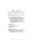
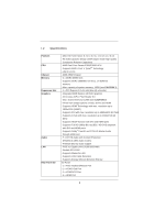
Platform CPU Chipset Memory Expansion Slot Graphics Audio LAN Rear Panel I/O - Mini-ITX Form Factor: 6.7-in x 6.7-in, 17.0 cm x 17.0 cm - All Solid Capacitor design (100% Japan-made high-quality Conductive Polymer Capacitors) - AMD Dual-Core Zacate E350/E350D APU - Supports AMD's Cool 'n' QuietTM - ASRock E350M1/USB3 | User Manual - Page 7
4 USB 2.0 ports) - 32Mb AMI BIOS - AMI UEFI Legal BIOS with GUI support - Supports "Plug and Play" - ACPI 1.1 Compliance Wake Up Events - Supports jumperfree - SMBIOS 2.3.1 Support - DRAM, FCH, +1V, +1.8V Voltage Multi-adjustment - Drivers, Utilities, AntiVirus Software (Trial Version), ASRock - ASRock E350M1/USB3 | User Manual - Page 8
ready power supply is required) (see CAUTION 10) * For detailed product information, please visit our website: http://www.asrock.com WARNING Please realize that there is a certain risk involved with overclocking, including adjusting the setting in the BIOS, applying Untied Overclocking Technology - ASRock E350M1/USB3 | User Manual - Page 9
into Standby mode (S1), Suspend to RAM (S3), hibernation mode (S4) or power off (S5). With APP Charger driver installed, you can easily enjoy the marvelous charging experience than ever. ASRock website: http://www.asrock.com/Feature/AppCharger/index.asp 7. SmartView, a new function of internet - ASRock E350M1/USB3 | User Manual - Page 10
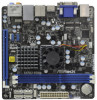
SPDIF eSATA3_1 USB 2.0 T: USB2 B: USB3 Super IO USB 2.0 T: USB4 B: USB5 Top: RJ-45 1 LAN PHY HD_AUDIO1 AUDIO CODEC 1 COM1 USB6_7 1 USB8_9 1 1 CIR1 RoHS 32Mb BIOS PCIE1 DX11 CHA_FAN2 PANEL 1 PLED PWRBTN 1 HDLED RESET SATA3_2 SATA3_4 SATA3_1 SATA3_3 SPEAKER1 1 7 8 9 10 11 12 - ASRock E350M1/USB3 | User Manual - Page 11
Rear Speaker (Black) 7 Optical SPDIF Out Port 8 Line In (Light Blue) ** 9 Front Speaker (Lime) 10 Microphone (Pink) 11 USB 2.0 Ports (USB45) 12 eSATA3 Port 13 VGA/HDMI Port 14 VGA/DVI-D Port 15 USB 3.0 Ports (USB01) * There are two LED next to the LAN port. Please refer to the table below for the - ASRock E350M1/USB3 | User Manual - Page 12
To enable Multi-Streaming function, you need to connect a front panel audio cable to the front panel audio header. After restarting your computer, you will find "Mixer" tool on your system. Please select "Mixer ToolBox" , click "Enable playback multi-streaming", and click "ok". Choose "2CH", "4CH - ASRock E350M1/USB3 | User Manual - Page 13
This is a Mini-ITX form factor (6.7" x 6.7", 17.0 x 17.0 cm) motherboard. Before you install the motherboard, study the configuration of your chassis to ensure that the motherboard fits into it. Make sure to unplug the power cord before installing or removing the motherboard. Failure to do - ASRock E350M1/USB3 | User Manual - Page 14
of Memory Modules (DIMM) E350M1/USB3 motherboard provides two 240-pin DDR3 (Double Data Rate 3) DIMM slots. It is not allowed to install a DDR or DDR2 memory module into DDR3 slot; otherwise, this motherboard and DIMM may be damaged. Installing a DIMM Please make sure to disconnect power supply - ASRock E350M1/USB3 | User Manual - Page 15
PCI Express slot on this motherboard. PCIE slot: PCIE1 (PCIE x16 slot; Blue) is used for PCI Express x4 lane width graphics cards. Installing an expansion card Step 1. Before installing the expansion card, please make sure that the power supply is switched off or the power cord is unplugged. Please - ASRock E350M1/USB3 | User Manual - Page 16
VGA card to this motherboard. This motherboard also provides independent display controllers for DVI-D, D-Sub and HDMI to support dual VGA output so function after your system boots. If you haven't installed onboard VGA driver yet, please install onboard VGA driver from our support CD to your system - ASRock E350M1/USB3 | User Manual - Page 17
function is supported on this motherboard. To use HDCP function with this motherboard, you need to adopt the monitor that supports HDCP function as well. Therefore, you can enjoy the superior display quality with high-definition HDCP encryption contents. Please refer to below instruction for more - ASRock E350M1/USB3 | User Manual - Page 18
need to clear the CMOS when you just finish updating the BIOS, you must boot up the system first, and then shut it down before you do the clear-CMOS action. Please be noted that the password, date, time, user default profile, 1394 GUID and MAC address will be cleared only if the CMOS - ASRock E350M1/USB3 | User Manual - Page 19
Audio Header (9-pin HD_AUDIO1) (see p.10 No. 20) GND PRESENCE# MIC_RET OUT_RET 1 OUT2_L J_SENSE OUT2_R MIC2_R MIC2_L 19 Besides four default USB 2.0 ports on the I/O panel, there are two USB 2.0 headers on this motherboard. Each USB 2.0 header can support two USB 2.0 ports. This header can be - ASRock E350M1/USB3 | User Manual - Page 20
Jack Sensing, but the panel wire on the chassis must support HDA to function correctly. Please follow the instruction in our manual and chassis manual to install your system. 2. If you use AC'97 audio panel, please install it to the front panel audio header as below: A. Connect Mic_IN (MIC) - ASRock E350M1/USB3 | User Manual - Page 21
-pin ATXPWR1) (see p.10 No. 7) 12 24 Please connect the CPU fan cable to the connector and match the black wire to the ground pin. CPU_FAN1 supports fan speed control. Please connect an ATX power supply to this connector. 1 13 Though this motherboard provides 24-pin ATX power connector, 12 24 - ASRock E350M1/USB3 | User Manual - Page 22
2.8 Serial ATA3 (SATA3) Hard Disks Installation This motherboard adopts AMD A50M chipset that supports Serial ATA3 (SATA3) hard disks. You may install SATA3 hard disks on this motherboard for internal storage devices. This section will guide you to install the SATA3 hard disks. STEP 1: Install the - ASRock E350M1/USB3 | User Manual - Page 23
SATA3 HDDs This motherboard supports Hot Plug function for SATA3 in AHCI mode. AMD A50M chipset provides hardware support for Advanced Host controller NOT set for RAID configuration, it is called "Hot Plug" for the action to insert and remove the SATA3 HDDs while the system is still power-on and in - ASRock E350M1/USB3 | User Manual - Page 24
installed into system properly. The latest SATA / SATAII / SATA3 driver is available on our support website: www.asrock.com 4. Make sure to use the SATA power cable & data cable, which are from our motherboard package. 5. Please follow below instructions step by step to reduce the risk of HDD crash - ASRock E350M1/USB3 | User Manual - Page 25
do follow below instruction sequence to process the Hot Plug, improper procedure will cause the SATA / SATAII / SATA3 HDD damage and data loss. Step 1 Please connect SATA power cable 1x4-pin end Step 2 Connect SATA data cable to (White) to the power supply 1x4-pin cable. the motherboard's SATAII - ASRock E350M1/USB3 | User Manual - Page 26
and listed on the support CD driver page. Please follow the order from up to bottom side to install those required drivers. Therefore, the drivers you install can work properly. 2.12 Installing Windows® 7 / 7 64-bit / VistaTM / VistaTM 64-bit / XP / XP 64-bit Without RAID Functions If you want - ASRock E350M1/USB3 | User Manual - Page 27
Using SATA / SATAII / STA3 HDDs without NCQ function STEP 1: Set up UEFI. A. Enter UEFI SETUP UTILITY Advanced screen Storage Configuration. B. Set the option "SATA Mode" to [IDE]. STEP 2: Install Windows® 7 / 7 64-bit / VistaTM / VistaTM 64-bit OS on your system. 27 - ASRock E350M1/USB3 | User Manual - Page 28
SETUP UTILITY to configure your system. The UEFI chip on the motherboard stores the UEFI SETUP UTILITY. You may run the UEFI SETUP UTILITY when you start up the computer. Please press or during the Power-On-Self-Test (POST) to enter the UEFI SETUP UTILITY, otherwise, POST will continue - ASRock E350M1/USB3 | User Manual - Page 29
3.1.2 Navigation Keys Please check the following table for the function description of each navigation key. Navigation Key(s) Function Description / Moves cursor left or right to select Screens / Moves cursor up or down to select items + / - To change option for the selected items - ASRock E350M1/USB3 | User Manual - Page 30
Screen In the OC Tweaker screen, you can set up overclocking features. DRAM Timing Control DRAM Frequency If [Auto] is selected, the motherboard will detect the memory module(s) inserted and assigns appropriate frequency automatically. Bank Interleaving Interleaving allows memory accesses to be - ASRock E350M1/USB3 | User Manual - Page 31
to Precharge (tRTP) Auto/Manual setting. The default is [Auto]. Four Activate Window (tFAW) Use this item to change Four Activate Window (tFAW) Auto/Manual setting. The default is [ [1.85V] to [2.10V]. The default value is [Auto]. User Default In this option, you are allowed to load and save three - ASRock E350M1/USB3 | User Manual - Page 32
Instant Flash ASRock Instant Flash is a UEFI flash utility embedded in Flash ROM. This convenient UEFI update tool allows you to update system UEFI without entering operating systems first like MS-DOS or Windows®. Just launch this tool and save the new UEFI file to your USB flash drive, floppy disk - ASRock E350M1/USB3 | User Manual - Page 33
]. If you install Windows® 7 / VistaTM and want to enable this function, please set this item to [Enabled]. Please note that enabling this function may reduce CPU voltage and memory frequency, and lead to system stability or compatibility issue with some memory modules or power supplies. Please set - ASRock E350M1/USB3 | User Manual - Page 34
3.4.2 North Bridge Configuration Integrated Graphics This allows you to select the boot graphic adapter priority. Configuration options: [Auto], [Disabled] and [Force]. If you select [Auto], the onboard VGA will be disabled when the PCI Express VGA - ASRock E350M1/USB3 | User Manual - Page 35
power state after an unexpected AC/power loss. If [Power Off] is selected, the AC/power remains off when the power recovers. If [Power On] is selected, the AC/power resumes and the system starts to boot up when the power recovers. Onboard LAN motherboard to submit Windows® VistaTM certification. 35 - ASRock E350M1/USB3 | User Manual - Page 36
this to select SATA mode. Configuration options: [IDE Mode] and [AHCI Mode]. The default value is [IDE Mode]. AHCI (Advanced Host Controller Interface) supports NCQ and other new features that will improve SATA disk performance but IDE mode does not have these advantages. SATA IDE Combined Mode This - ASRock E350M1/USB3 | User Manual - Page 37
3.4.5 Super IO Configuration Serial Port Use this item to enable or disable the onboard serial port. Serial Port Address Use this item to set the address for the onboard serial port. Configuration options: [Auto], [3F8 / IRQ4], [2F8 / IRQ3], [3E8 / IRQ4], [2E8 / IRQ3]. 37 - ASRock E350M1/USB3 | User Manual - Page 38
ACPI Configuration Suspend to RAM Use this item to select whether to auto-detect or disable the Suspend-toRAM feature. Select [Auto] will enable this feature if the OS supports it. Check Ready Bit Use this item to enable or disable the feature Check Ready Bit. PS/2 Keyboard Power On Use this item - ASRock E350M1/USB3 | User Manual - Page 39
compatibility issue, it is recommended to select [Disabled] to enter OS. [UEFI Setup Only] - USB devices are allowed to use only under UEFI setup and Windows / Linux OS. Legacy USB 3.0 Support Use this option to enable or disable legacy support for USB 3.0 devices. The default value is [Enabled]. 39 - ASRock E350M1/USB3 | User Manual - Page 40
on your system, including the parameters of the CPU temperature, motherboard temperature, CPU fan speed, chassis fan speed, and the critical to set the chassis fan 1 speed. Configuration options: [Full On] and [Manual Mode]. The default is value [Full On]. Chassis Fan 2 Setting This allows you - ASRock E350M1/USB3 | User Manual - Page 41
options: [Enabled] and [Disabled]. The default value is [Enabled]. Boot Failure Guard Count Enable or disable the feature of Boot Failure Guard Count. Boot From Onboard LAN Use this item to enable or disable the Boot From Onboard LAN feature. Boot Failure Guard Enable or disable the feature of - ASRock E350M1/USB3 | User Manual - Page 42
3.7 Security Screen In this section, you may set or change the supervisor/user password for the system. For the user password, you may also clear it. 42 - ASRock E350M1/USB3 | User Manual - Page 43
3.8 Exit Screen Save Changes and Exit When you select this option, it will pop-out the following message, "Save configuration changes and exit setup?" Select [OK] to save the changes and exit the UEFI SETUP UTILITY. Discard Changes and Exit When you select this option, it will pop-out the following - ASRock E350M1/USB3 | User Manual - Page 44
install the necessary drivers to activate the devices. 4.2.3 Utilities Menu The Utilities Menu shows the applications software that the motherboard supports. Click on a specific item then follow the installation wizard to install it. 4.2.4 Contact Information If you need to contact ASRock or want to - ASRock E350M1/USB3 | User Manual - Page 45
press to launch boot menu at system POST and choose the item "UEFI:xxx" to boot. 4. Start Windows® installation. 5. If you install Windows® 7 64-bit OS, OS will be formatted by GPT (GUID Partition Table). Please install the hotfix file from Microsoft®: http://support.microsoft.com/kb/979903 45 - ASRock E350M1/USB3 | User Manual - Page 46
Installation Guide This motherboard is equipped with a 4-pin CIR header (CIR1, see page 10, No. 17), which is used to connect the Remote Receiver. Please refer to below procedure for installing the Remote Receiver. 1. Find the CIR header located under the USB 2.0 header (USB8_9, see page 10, No
-
 1
1 -
 2
2 -
 3
3 -
 4
4 -
 5
5 -
 6
6 -
 7
7 -
8
-
9
-
10
-
11
-
12
-
13
-
14
-
15
-
16
-
17
-
18
-
19
-
20
-
21
-
22
-
23
-
24
-
25
-
26
-
27
-
28
-
29
-
30
-
31
-
32
-
33
-
34
-
35
-
36
-
37
-
38
-
39
-
40
-
41
-
42
-
43
-
44
-
45
-
46
 |
 |

1
E350M1/USB3
User Manual
Version 1.1
Published June 2011
Copyright©2011 ASRock INC. All rights reserved.