ASRock E350M1/USB3 User Manual - Page 46
Remote Receiver Installation Guide
 |
View all ASRock E350M1/USB3 manuals
Add to My Manuals
Save this manual to your list of manuals |
Page 46 highlights
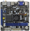
Remote Receiver Installation Guide This motherboard is equipped with a 4-pin CIR header (CIR1, see page 10, No. 17), which is used to connect the Remote Receiver. Please refer to below procedure for installing the Remote Receiver. 1. Find the CIR header located under the USB 2.0 header (USB8_9, see page 10, No. 18) on this motherboard. USB 2.0 header (9-pin, blue) CIR header (4-pin, white) 2. Connect the front USB cable to the USB 2.0 header (as below, pin 1-5) and the CIR header. Please make sure the wire assignments and the pin assignments are matched correctly. USB_PWR PP+ GND DUMMY 1 23 45 GND IRTX IRRX ATX+5VSB 3. Install the Remote Receiver to the front USB port. If the Remote Receiver cannot successfully receive the infrared signals from the Remote Controller, please try to install it to the other front USB port. * Only one of the front USB port can support CIR function. When the CIR function is enabled, the other port will remain USB function. * The Remote Receiver is used for front USB only. Please do not use the rear USB bracket to connect it on the rear panel. The Remote Receiver is able to receive the multi-direction infrared signals (top, down and front), which is compatible with most of the chassis on the market. * The Remote Receiver and Remote Controller are not bundled with this motherboard and may be sold separately in the near future. Please visit our website for further information: http://www.asrock.com 46
-
 1
1 -
2
-
3
-
4
-
5
-
6
-
7
-
8
-
9
-
10
-
11
-
12
-
13
-
14
-
15
-
16
-
17
-
18
-
19
-
20
-
21
-
22
-
23
-
24
-
25
-
26
-
27
-
28
-
29
-
30
-
31
-
32
-
33
-
34
-
35
-
36
-
37
-
38
-
39
-
40
-
 41
41 -
 42
42 -
 43
43 -
 44
44 -
 45
45 -
 46
46
 |
 |
