ASRock FM2A75M-ITX User Manual - Page 20
Expansion Slot PCI Express Slot, Installing an expansion card - r 20 motherboard
 |
View all ASRock FM2A75M-ITX manuals
Add to My Manuals
Save this manual to your list of manuals |
Page 20 highlights
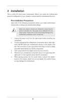
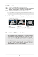
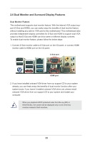
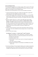
2.4 Expansion Slot (PCI Express Slot) There is 1 PCI Express slot on this motherboard. PCIE Slot: PCIE1 (PCIE x16 slot) is used for PCI Express x16 lane width graphics cards. Installing an expansion card Step 1. Before installing the expansion card, please make sure that the power supply is switched off or the power cord is unplugged. Please read the documentation of the expansion card and make necessary hardware settings for the card before you start the installation. Step 2. Remove the system unit cover (if your motherboard is already installed in a chassis). Step 3. Remove the bracket facing the slot that you intend to use. Keep the screws for later use. Step 4. Align the card connector with the slot and press firmly until the card is completely seated on the slot. Step 5. Fasten the card to the chassis with screws. Step 6. Replace the system cover. 20
-
 1
1 -
2
-
3
-
4
-
5
-
6
-
7
-
8
-
9
-
10
-
11
-
12
-
13
-
14
-
 15
15 -
 16
16 -
 17
17 -
 18
18 -
 19
19 -
 20
20 -
 21
21 -
 22
22 -
 23
23 -
 24
24 -
 25
25 -
26
-
27
-
28
-
29
-
30
-
31
-
32
-
33
-
34
-
35
-
36
-
37
-
38
-
39
-
40
-
41
-
42
-
43
-
44
-
45
-
46
-
47
-
48
-
49
-
50
-
51
-
52
-
53
-
54
-
55
-
56
-
57
-
58
-
59
-
60
-
61
-
62
-
63
-
64
-
65
 |
 |