ASRock Fatal1ty P67 Performance Quick Installation Guide
ASRock Fatal1ty P67 Performance Manual
 |
View all ASRock Fatal1ty P67 Performance manuals
Add to My Manuals
Save this manual to your list of manuals |
ASRock Fatal1ty P67 Performance manual content summary:
- ASRock Fatal1ty P67 Performance | Quick Installation Guide - Page 1
professional gaming in 1999 when I entered the CPL (Cyberathlete Professional Alien vs. Predator part in shaping eSports into what it is today and for being the prime representative of this young sport. He has become the figurehead for eSports worldwide". 1 Fatal1ty P67 Performance Series Motherboard - ASRock Fatal1ty P67 Performance | Quick Installation Guide - Page 2
The Fatal1ty name, Fatal1ty logos and the Fatal1ty likeness are registered trademarks of Fatal1ty, Inc., and are used under license. © 2011 Fatal1ty, Inc. All rights reserved. All other trademarks are the property of their respective owners. 2 Fatal1ty P67 Performance Series Motherboard English - ASRock Fatal1ty P67 Performance | Quick Installation Guide - Page 3
are registered trademarks of Fatal1ty, Inc., and are used under license. © 2011 Fatal1ty, Inc. All rights reserved. All other trademarks are the property of their respective owners. Fatal1ty website: www.fatal1ty.com Published April 2011 3 Fatal1ty P67 Performance Series Motherboard English - ASRock Fatal1ty P67 Performance | Quick Installation Guide - Page 4
Fatal1ty P67 Performance 37 PCIE2 IDE1 CHA_FAN2 9 10 USB 3.0 PCI Express 2.0 36 PCIE3 CMOS 35 Battery Super I/O PCIE4 1 CLRCMOS1 64Mb 11 BIOS PLED1 1 12 Intel SPEAKER1 1 13 PANEL1 PLED PWRBTN P67 ATX 1155-Pin CPU Socket Fatal1ty P67 Performance Series Motherboard English - ASRock Fatal1ty P67 Performance | Quick Installation Guide - Page 5
10 8 11 18 17 16 15 1 PS/2 Mouse Port (Green) 2 Coaxial SPDIF Out Port 3 Fatal1ty Mouse Port (USB6) 4 USB 2.0 Port (USB7) * 5 LAN RJ-45 Port 6 Side Speaker ( . 8) (No. 6) 2 V -- -- -- 4 V V -- -- 6 V V V -- 8 V V V V English 5 Fatal1ty P67 Performance Series Motherboard - ASRock Fatal1ty P67 Performance | Quick Installation Guide - Page 6
Primary output" to use Rear Speaker, Central/Bass, and Front Speaker, or select "Realtek HDA Audio 2nd output" to use front panel audio. *** eSATA3 connector supports SATA Gen3 in cable 1M. English 6 Fatal1ty P67 Performance Series Motherboard - ASRock Fatal1ty P67 Performance | Quick Installation Guide - Page 7
... To get better performance in Windows® 7 / 7 64-bit / VistaTM / VistaTM 64bit, it is recommended to set the BIOS option in Storage Configuration to AHCI mode. For the BIOS setup, please refer to the "User Manual" in our support CD for details. 7 Fatal1ty P67 Performance Series Motherboard English - ASRock Fatal1ty P67 Performance | Quick Installation Guide - Page 8
Capacitors) - Supports 2nd Generation Intel® CoreTM i7 / i5 / i3 in LGA1155 Package - Advanced V8 Power Phase Design - Supports Intel® Turbo Boost 2.0 Technology - Supports K-Series unlocked CPU - Supports Hyper-Threading Technology (see CAUTION 1) - Intel® P67 - Dual Channel DDR3 Memory Technology - ASRock Fatal1ty P67 Performance | Quick Installation Guide - Page 9
- Drivers, Utilities, AntiVirus Software (Trial Version), Software Suite (CyberLink DVD Suite - OEM and Trial; Creative Sound Blaster X-Fi MB - Trial) - F-Stream (see CAUTION 6) - ASRock Instant Boot - ASRock Instant Flash (see CAUTION 7) English 9 Fatal1ty P67 Performance Series Motherboard - ASRock Fatal1ty P67 Performance | Quick Installation Guide - Page 10
tools. Overclocking may affect your system stability, or even cause damage to the components and devices of your system. It should be done at your own risk and expense. We are not responsible for possible damage caused by overclocking. English 10 Fatal1ty P67 Performance Series Motherboard - ASRock Fatal1ty P67 Performance | Quick Installation Guide - Page 11
oppy disk or hard drive, then you can update your BIOS only in a few clicks without preparing an additional floppy diskette or other complicated flash utility. Please be noted that the USB flash drive or hard drive must use FAT32/16/12 file system. 11 Fatal1ty P67 Performance Series Motherboard English - ASRock Fatal1ty P67 Performance | Quick Installation Guide - Page 12
supports continuous charging when your PC enters into Standby mode (S1), Suspend to RAM (S3), hibernation mode (S4) or power off (S5). With APP Charger driver different CPU cooler types, Socket LGA 775, LGA 1155 and LGA 1156. Please be noticed Fatal1ty P67 Performance Series Motherboard English - ASRock Fatal1ty P67 Performance | Quick Installation Guide - Page 13
the 1155-Pin CPU into the socket, please check if the CPU surface is unclean or if there is any bent pin on the socket. Do not force to insert the CPU into the socket if above situation is found. Otherwise, the CPU will be seriously damaged. English 13 Fatal1ty P67 Performance Series Motherboard - ASRock Fatal1ty P67 Performance | Quick Installation Guide - Page 14
returning the motherboard for after service. Step 3. Insert the 1155-Pin CPU 1155-Pin CPU alignment key 1155-Pin Socket For proper inserting, please ensure to match the two orientation key notches of the CPU with the two alignment keys of the socket. 14 Fatal1ty P67 Performance Series Motherboard - ASRock Fatal1ty P67 Performance | Quick Installation Guide - Page 15
that this motherboard supports Combo Cooler Option (C.C.O.), which provides the flexible option to adopt three different CPU cooler types, Socket LGA 775, LGA 1155 and LGA 1156. The white throughholes are for Socket LGA 1155/1156 CPU fan. 15 Fatal1ty P67 Performance Series Motherboard English - ASRock Fatal1ty P67 Performance | Quick Installation Guide - Page 16
a DDR or DDR2 memory module into DDR3 slot; otherwise, this motherboard and DIMM may be damaged. 5. Some DDR3 1GB double-sided DIMMs with 16 chips may not work on this motherboard. It is not recommended to install them on this motherboard. English 16 Fatal1ty P67 Performance Series Motherboard - ASRock Fatal1ty P67 Performance | Quick Installation Guide - Page 17
damage to the motherboard and the DIMM if you force the DIMM into the slot at incorrect orientation. Step 3. Firmly insert the DIMM into the slot until the retaining clips at both ends fully snap back in place and the DIMM is properly seated. English 17 Fatal1ty P67 Performance Series Motherboard - ASRock Fatal1ty P67 Performance | Quick Installation Guide - Page 18
the card before you start the installation. Step 2. Remove the system unit cover (if your motherboard is already installed in a chassis). Step 3. Remove the bracket facing the slot that you intend with screws. Step 6. Replace the system cover. 18 Fatal1ty P67 Performance Series Motherboard English - ASRock Fatal1ty P67 Performance | Quick Installation Guide - Page 19
after you update the BIOS. If you need to clear the CMOS when you just finish updating the BIOS, you GUID and MAC address will be cleared only if the CMOS battery is removed. The Clear CMOS Switch has the same function as the Clear CMOS jumper. English 19 Fatal1ty P67 Performance Series Motherboard - ASRock Fatal1ty P67 Performance | Quick Installation Guide - Page 20
of the SATA data Data Cable cable can be connected to the (Optional) SATA / SATAII / SATA3 hard disk or the SATAII / SATA3 connector on this motherboard. 20 Fatal1ty P67 Performance Series Motherboard English - ASRock Fatal1ty P67 Performance | Quick Installation Guide - Page 21
manual and chassis manual to install your system. 2. If you use AC'97 audio panel, please install it to the front panel audio header as below: A. Connect Mic_IN (MIC) to MIC2_L. B. Connect Audio_R (RIN) to OUT2_R and Audio_L (LIN) to OUT2_L. English 21 Fatal1ty P67 Performance Series Motherboard - ASRock Fatal1ty P67 Performance | Quick Installation Guide - Page 22
for AC'97 audio panel. E. To activate the front mic. For Windows® XP / XP 64-bit OS: Select "Mixer". Select "Recorder". Then click "FrontMic". For Windows® 7 / 7 64-bit / VistaTM / VistaTM 64-bit OS connect the chassis speaker to this header. 22 Fatal1ty P67 Performance Series Motherboard English - ASRock Fatal1ty P67 Performance | Quick Installation Guide - Page 23
wire to the ground pin. Though this motherboard provides 4-Pin CPU fan (Quiet Fan) support, the 3-Pin CPU fan still can ATX Power Connector (24-pin ATXPWR1) (see p.4 No. 7) 12 24 1 13 Please connect an ATX power supply to this connector. English 23 Fatal1ty P67 Performance Series Motherboard - ASRock Fatal1ty P67 Performance | Quick Installation Guide - Page 24
5 Serial port Header (9-pin COM1) (see p.4 No. 31) 4-Pin ATX 12V Power Supply Installation 4 1 This COM1 header supports a serial port module. HDMI_SPDIF Header (2-pin HDMI_SPDIF1) (see p.4 No. 33) of HDMI VGA card to this header. English 24 Fatal1ty P67 Performance Series Motherboard - ASRock Fatal1ty P67 Performance | Quick Installation Guide - Page 25
2.7 Smart Switches The motherboard has three smart switches: power switch, reset switch and clear CMOS switch, allowing users to quickly No. 17) clr CMOS Clear CMOS Switch is a smart switch, allowing users to quickly clear the CMOS values. English 25 Fatal1ty P67 Performance Series Motherboard - ASRock Fatal1ty P67 Performance | Quick Installation Guide - Page 26
, which makes troubleshooting even easier. memory initialization. Application Processor(s) (AP) initialization CPU post-memory initialization. Boot Strap Processor (BSP) selection CPU post-memory initialization. System Management Mode (SMM) initialization Fatal1ty P67 Performance Series Motherboard - ASRock Fatal1ty P67 Performance | Quick Installation Guide - Page 27
is not available Recovery capsule is not found Invalid recovery capsule Reserved for future AMI error codes DXE Core is started NVRAM initialization English 27 Fatal1ty P67 Performance Series Motherboard - ASRock Fatal1ty P67 Performance | Quick Installation Guide - Page 28
0xA2 0xA3 0xA4 0xA5 28 Installation of the South Bridge Runtime Services CPU DXE initialization is started CPU DXE initialization (CPU module speci Boot Device Selection (BDS) phase is started Driver connecting is started PCI Bus initialization is started Fatal1ty P67 Performance Series Motherboard - ASRock Fatal1ty P67 Performance | Quick Installation Guide - Page 29
Status Codes section below) Ready To Boot event Legacy Boot event Exit Boot Services event Runtime Set Virtual Address MAP Begin Runtime Set Virtual Address MAP End Legacy returned error) Flash update is failed Reset protocol is not available English 29 Fatal1ty P67 Performance Series Motherboard - ASRock Fatal1ty P67 Performance | Quick Installation Guide - Page 30
SATA3 HDDs with RAID functions, please refer to the document at the following path in the Support CD for detailed procedures: ..\ RAID Installation Guide 2.11 Installing Windows® 7 / 7 STEP 2: Install Windows® XP / XP 64-bit OS on your system. 30 Fatal1ty P67 Performance Series Motherboard English - ASRock Fatal1ty P67 Performance | Quick Installation Guide - Page 31
bit Without RAID Functions If you want to install Windows® 7 / 7 64-bit / VistaTM / VistaTM 64-bit OS on your SATA / SATAII / SATA3 HDDs without RAID functions, STEP 2: Install Windows® 7 / 7 64-bit / VistaTM / VistaTM 64-bit OS on your system. 31 Fatal1ty P67 Performance Series Motherboard English - ASRock Fatal1ty P67 Performance | Quick Installation Guide - Page 32
about BIOS Setup, please refer to the User Manual (PDF file) contained in the Support CD. 4. Software Support CD information This motherboard supports various Microsoft® Windows® from the BIN folder in the Support CD to display the menus. 32 Fatal1ty P67 Performance Series Motherboard English - ASRock Fatal1ty P67 Performance | Quick Installation Guide - Page 33
ötigen, besuchen Sie bitte unsere Webseite. 1.1 Kartoninhalt Fatal1ty P67 Performance Series Motherboard (ATX-Formfaktor: 30.5 cm x 24.4 cm; 12.0 Zoll x 9.6 Zoll) Fatal1ty P67 Performance Series Schnellinstallationsanleitung Fatal1ty P67 Performance Series Support-CD Ein 80-adriges Ultra-ATA 66/100 - ASRock Fatal1ty P67 Performance | Quick Installation Guide - Page 34
- 1 x PS/2-Mausanschluss - 1 x PS/2-Tastaturanschluss - 1 x Koaxial-SPDIF-Ausgang - 1 x optischer SPDIF-Ausgang - 5 x Standard-USB 2.0-Anschlüsse - 1 x Fatal1ty Mausanschluss (USB 2.0) - 1 x eSATA3-Anschluss - 2 x Standard-USB 3.0-Anschlüsse 34 Fatal1ty P67 Performance Series Motherboard Deutsch - ASRock Fatal1ty P67 Performance | Quick Installation Guide - Page 35
BIOS - 64Mb AMI BIOS - AMIs Legal BIOS UEFI mit GUI-Unterstützung - Unterstützung für "Plug and Play" - ACPI 1.1-Weckfunktionen - JumperFree-Übertaktungstechnologie - SMBIOS 2.3.1 - DRAM, PCH, CPU PLL, VTT, VCSA Stromspannung Multianpassung 35 Fatal1ty P67 Performance Series Motherboard - ASRock Fatal1ty P67 Performance | Quick Installation Guide - Page 36
äte Ihres Systems beschädigen. Es geschieht dann auf eigene Gefahr und auf Ihre Kosten. Wir übernehmen keine Verantwortung für mögliche Schäden, die aufgrund von Overclocking verursacht wurden. Deutsch 36 Fatal1ty P67 Performance Series Motherboard - ASRock Fatal1ty P67 Performance | Quick Installation Guide - Page 37
Sie Ihr BIOS mit nur wenigen Klickvorgängen ohne Bereitstellung einer zusätzlichen Diskette oder eines anderen komplizierten Flash-Programms aktualisieren. Achten Sie darauf, dass das USB-Flash-Laufwerk oder die Festplatte das Dateisystem FAT32/16/12 benutzen muss. 37 Fatal1ty P67 Performance Series - ASRock Fatal1ty P67 Performance | Quick Installation Guide - Page 38
Windows®-Betriebssystemen 7 / 7, 64 Bit / VistaTM / VistaTM 64 Bit und dem Internet Explorer ab Version 8 nutzen. 10. ASRocks Socket LGA 775, LGA 1155 und LGA 1156. Beachten Sie bitte, dass nicht alle 775 und 1156 CPU-Lüfter verwendet werden können. 38 Fatal1ty P67 Performance Series Motherboard - ASRock Fatal1ty P67 Performance | Quick Installation Guide - Page 39
EuP steht für Energy Using Product und kennzeichnet die Ökodesign- sind ein EuP-fähiges Motherboard und eine EuP-fähige Stromversorgung erforderlich. Gemäß einer Empfehlung von Intel muss eine EuP-fähige der Stromversorgung abzufragen. 39 Fatal1ty P67 Performance Series Motherboard Deutsch - ASRock Fatal1ty P67 Performance | Quick Installation Guide - Page 40
Sockel Übersicht Bevor Sie die 1155-Pin CPU in den Sockel sitzen, prüfen Sie bitte, ob die CPU-Oberfläche sauber ist und keine der Kontakte verbogen sind. Setzen Sie die CPU nicht mit Gewalt in den Sockel, dies kann die CPU schwer beschädigen. Deutsch 40 Fatal1ty P67 Performance Series Motherboard - ASRock Fatal1ty P67 Performance | Quick Installation Guide - Page 41
Heat Sink - integrierter Kühlkörper) nach oben. Suchen Sie Pin 1 und die zwei Orientierungseinkerbungen. Orientierungskerbe Ausrichtungsmarkierung Pin1 Orientierungskerbe 1155-Pin CPU Ausrichtungsmarkierung 1155-Pin Sockel Pin1 41 Fatal1ty P67 Performance Series Motherboard Deutsch - ASRock Fatal1ty P67 Performance | Quick Installation Guide - Page 42
(IHS). Schritt 4-2. Drücken Sie leicht auf die Ladeplatte und schließen Sie den Ladehebel. Schritt 4-3. Sichern Sie Ladehebel und Ladeplatte mithilfe des Hebelverschlusses. 42 Fatal1ty P67 Performance Series Motherboard Deutsch - ASRock Fatal1ty P67 Performance | Quick Installation Guide - Page 43
-Kühleroption unterstützt, die eine flexible Möglichkeit zur Aufnahme von drei verschiedenen CPU-Kühlertypen, Socket LGA 775, LGA 1155 und LGA 1156, bietet. Das weiße Durchgangsloch ist für den CPU-Lüfter im Socket LGA 1155/1156 vorgesehen. Deutsch 43 Fatal1ty P67 Performance Series Motherboard - ASRock Fatal1ty P67 Performance | Quick Installation Guide - Page 44
; andernfalls könnten Motherboard und DIMMs beschädigt werden. 5. Einige doppelseitige 1 GB-DDR3-DIMMs mit 16 Chips funktionieren möglicherweise nicht auf diesem Motherboard. Wir empfehlen, sie nicht auf diesem Motherboard zu installieren. 44 Fatal1ty P67 Performance Series Motherboard Deutsch - ASRock Fatal1ty P67 Performance | Quick Installation Guide - Page 45
die Steckplätze, so dass die Halteklammern an beiden Enden des Moduls einschnappen und das DIMM-Modul fest an Ort und Stelle sitzt. Deutsch 45 Fatal1ty P67 Performance Series Motherboard - ASRock Fatal1ty P67 Performance | Quick Installation Guide - Page 46
ätze (PCI-Steckplätze und PCI Express-Steckplätze) Es gibt einen 3 PCI-Steckplätze und 4 PCI Express-Steckplätze am Fatal1ty P67 Performance Series Motherboard. PCI-Slots: PCI-Slots werden zur Installation von Erweiterungskarten mit dem 32bit PCI-Interface genutzt. PCI Express-Slots: PCIE1 / PCIE3 - ASRock Fatal1ty P67 Performance | Quick Installation Guide - Page 47
der BIOS-Aktualisierung löschen. Wenn Sie das CMOS nach Abschluss der BIOS- GUID und MAC-Adresse nur gelöscht werden, wenn die CMOS-Batterie entfernt wird. Der CMOS löschen-Schalter hat dieselbe Funktion wie der CMOS löschen-Jumper. Deutsch 47 Fatal1ty P67 Performance Series Motherboard - ASRock Fatal1ty P67 Performance | Quick Installation Guide - Page 48
) (39-pin IDE1, siehe S.4 - No. 8) Blauer Anschluss Schwarzer Anschluss zum Motherboard zur Festplatte 80-adriges ATA 66/100/133 Kabel Hinweis: Details entnehmen Sie bitte den ermöglicht eine Datenübertragungsrate bis 6,0 Gb/s. 48 Fatal1ty P67 Performance Series Motherboard Deutsch - ASRock Fatal1ty P67 Performance | Quick Installation Guide - Page 49
üblichen USB 2.0-Ports an den I/O-Anschlüssen befinden sich drei USB 2.0Anschlussleisten am Motherboard. Pro USB 2.0Anschlussleiste werden zwei USB 2.0-Ports unterstützt. Infrarot-Modul-Header (5-pin IR1 und Kontrolle über Audio-Geräte. 49 Fatal1ty P67 Performance Series Motherboard Deutsch - ASRock Fatal1ty P67 Performance | Quick Installation Guide - Page 50
AC'97-Audioleiste angeschlossen werden. E. So aktivieren Sie das Mikrofon an der Vorderseite. Bei den Betriebssystemen Windows® XP / XP 64 Bit: Wählen Sie „Mixer". Wählen Sie „Recorder" (Rekorder). Klicken Modi S3/S4 befindet oder ausgeschaltet ist (S5). 50 Fatal1ty P67 Performance Series Motherboard - ASRock Fatal1ty P67 Performance | Quick Installation Guide - Page 51
-Zustand (ausgeschaltet) leuchtet die LED nicht. Verbinden Sie die Lüfterkabel mit den Lüfteranschlüssen, wobei der schwarze Draht an den Schutzleiterstift angeschlossen wird. Deutsch 51 Fatal1ty P67 Performance Series Motherboard - ASRock Fatal1ty P67 Performance | Quick Installation Guide - Page 52
4-Pin ATX 12V Energieversorgung adoptieren. Um die 4-Pin ATX Energieversorgung zu verwenden, stecken Sie bitte Ihre Energieversorgung zusammen mit dem Pin 1 und Pin 5 ein. 8 5 Installation der 4-Pin ATX 12V Energieversorgung 4 1 52 Fatal1ty P67 Performance Series Motherboard Deutsch - ASRock Fatal1ty P67 Performance | Quick Installation Guide - Page 53
wie Fernsehgeräten, Projektoren, LCD-Geräten an das System. Bitte verbinden Sie den HDMI_SPDIF-Anschluss der HDMI-VGA-Karte mit diesem Anschluss. Deutsch 53 Fatal1ty P67 Performance Series Motherboard - ASRock Fatal1ty P67 Performance | Quick Installation Guide - Page 54
2.7 Schnellschalter Dieses Motherboard besitzt drei Schnellschalter: Netzschalter, Rücksetzschalter (Reset) und CMOS löschen-Schalter, mit denen löschen-Schalter ist ein Schnellschalter, mit dem Benutzer die CMOS-Werte schnell löschen können. Deutsch 54 Fatal1ty P67 Performance Series Motherboard - ASRock Fatal1ty P67 Performance | Quick Installation Guide - Page 55
CD finden: ..\ RAID Installation Guide 2.11 Windows® 7 / 7 64-Bit / VistaTM / VistaTM 64-Bit / XP / XP 64-Bit ohne RAID-Funktionalität installieren Wenn Sie Windows® 7 / 7 IDE]. SCHRITT 2: Installieren Sie Windows® XP / XP 64-Bit in Ihrem System. 55 Fatal1ty P67 Performance Series Motherboard Deutsch - ASRock Fatal1ty P67 Performance | Quick Installation Guide - Page 56
VistaTM 64-Bit ohne RAID-Funktionalität installieren Wenn Sie Windows® 7 / 7 64-Bit / VistaTM / VistaTM 64-Bit ohne RAID-Funktionalität auf Ihren SATA SCHRITT 2: Installieren Sie Windows® 7 / 7 64-Bit / VistaTM / VistaTM 64-Bit in Ihrem System. 56 Fatal1ty P67 Performance Series Motherboard Deutsch - ASRock Fatal1ty P67 Performance | Quick Installation Guide - Page 57
der Support-CD, um die Menüs aufzurufen. Das Setup-Programm soll es Ihnen so leicht wie möglich machen. Es ist menügesteuert, d.h. Sie können in den verschiedenen Untermenüs Ihre Auswahl treffen und die Programme werden dann automatisch installiert. 57 Fatal1ty P67 Performance Series Motherboard - ASRock Fatal1ty P67 Performance | Quick Installation Guide - Page 58
sous Windows® 7 / 7 64 bits / VistaTM / VistaTM 64 bits, il est recommandé de paramétrer l'option BIOS dans Configuration de stockage en mode AHCI. Pour plus de détails sur l'installation BIOS, référez-vous au "Mode d'emploi" sur votre CD de support. 58 Fatal1ty P67 Performance Series Motherboard - ASRock Fatal1ty P67 Performance | Quick Installation Guide - Page 59
étique) 802.3az I/O Panel - 1 x port souris PS/2 - 1 x port clavier PS/2 - 1 x Port de sortie coaxial SPDIF - 1 x Port de sortie optique SPDIF - 5 x ports USB 2.0 par défaut 59 Fatal1ty P67 Performance Series Motherboard Français - ASRock Fatal1ty P67 Performance | Quick Installation Guide - Page 60
ées pouvant aller jusqu'à 3.0Go/s, supporte RAID (RAID 0, RAID 1, RAID 10, RAID 5 et Intel Rapid Storage), NCQ, AHCI et « br. 24 connecteur d'alimentation ATX - br. 8 connecteur d'alimentation 12V ATX - Connecteur audio panneau avant avec LED Français 60 Fatal1ty P67 Performance Series Motherboard - ASRock Fatal1ty P67 Performance | Quick Installation Guide - Page 61
vitesses - Monitoring de la tension: +12V, +5V, +3.3V, Vcore - Microsoft® Windows® 7 / 7 64-bit / VistaTM / VistaTM 64-bit / XP / XP 64-bit - FCC, CE, WHQL - Prêt pour ErP/EuP (alimentation Prêt pour ErP/EuP requise) (voir ATTENTION 15) Français 61 Fatal1ty P67 Performance Series Motherboard - ASRock Fatal1ty P67 Performance | Quick Installation Guide - Page 62
effectuer l'overclocking, y compris ajuster les réglages du BIOS, appliquer la technologie Untied Overclocking, ou utiliser des outils de tiers pour l'overclocking. L'overclocking peut affecter , sans diminuer les performances de l'ordinateur. 62 Fatal1ty P67 Performance Series Motherboard Français - ASRock Fatal1ty P67 Performance | Quick Installation Guide - Page 63
Windows®. Com este utilitário, poderá premir a tecla durante o teste de arranque POST ou premir a tecla para exibir o menu de configuração do BIOS para aceder ao ASRock mode Veille (S1), Suspension à la RAM (S3), hibernation (S4) ou hors Fatal1ty P67 Performance Series Motherboard Français - ASRock Fatal1ty P67 Performance | Quick Installation Guide - Page 64
sockets LGA 775, LGA 1155 et LGA 1156. Veuillez noter que tous les ventilateurs de CPU 775 et 1156 ne peuvent pas être utilisés. 15. EuP, qui signifie Energy Using Product les suggestions d'Intel', l'alimentation électrique Fatal1ty P67 Performance Series Motherboard Français - ASRock Fatal1ty P67 Performance | Quick Installation Guide - Page 65
socket, veuillez vérifier que la surface du processeur est bien propre, et qu'il n'y a aucune broche tordue sur le socket. Si c'est le cas, ne forcez pas pour insérer le processeur dans le socket. Sinon, le processeur sera gravement endommagé. Français 65 Fatal1ty P67 Performance Series Motherboard - ASRock Fatal1ty P67 Performance | Quick Installation Guide - Page 66
mis en place si vous renvoyez la carte mère pour service après vente. Etape 3. Insérez le processeur 1155 broches : Etape 3-1. Tenez le processeur par ses bords 1 broche 1 Encoche d'orientation Détrompeur Socket 1155 broches Processeur 1155 broches 66 Fatal1ty P67 Performance Series Motherboard - ASRock Fatal1ty P67 Performance | Quick Installation Guide - Page 67
aux manuels d'instructions de votre ventilateur 1155 broches. Etape 1. Appliquez le matériau d'interface thermique au centre de IHS sur la surface du socket. (Appliquez le matériau d'interface thermique) Apply Thermal Interface Material Français 67 Fatal1ty P67 Performance Series Motherboard - ASRock Fatal1ty P67 Performance | Quick Installation Guide - Page 68
Cooler Option (C.C.O.), qui offre un choix flexible pour adopter trois types différents de refroidisseurs de CPU, les sockets LGA 775, LGA 1155 et LGA 1156. Les trous traversant blancs sont pour le ventilateur de CPU au socket LGA 1155/1156. Français 68 Fatal1ty P67 Performance Series Motherboard - ASRock Fatal1ty P67 Performance | Quick Installation Guide - Page 69
m émoire [DIMM] La carte mère Fatal1ty P67 Performance Series dispose de quatre emplacements DIMM DDR3 (Double Data Rate 3) de 240-broches, et supporte la Technologie de Mémoire à Canal Double. mère et les DIMM pourraient être endommagés. Français 69 Fatal1ty P67 Performance Series Motherboard - ASRock Fatal1ty P67 Performance | Quick Installation Guide - Page 70
jusqu'à ce que les clips de maintien situés aux deux extrémités se ferment complètement et que le module DIMM soit inséré correctement. 70 Fatal1ty P67 Performance Series Motherboard - ASRock Fatal1ty P67 Performance | Quick Installation Guide - Page 71
PCI Express) Il y a 3 ports PCI et 4 ports PCI Express sur la carte mère Fatal1ty P67 Performance Series. Slots PCI: Les slots PCI sont utilisés pour installer des cartes d'extension dotées d'une interface sur le châssis à l'aide d'une vis. 71 Fatal1ty P67 Performance Series Motherboard Français - ASRock Fatal1ty P67 Performance | Quick Installation Guide - Page 72
BIOS. Si vous avez besoin d'effacer le CMOS après avoir mis à jour le BIOS, GUID et l'adresse MAC seront effacés seulement si la batterie du CMOS est enlevée. Le commutateur Effacer CMOS présente la même fonction que le cavalier Effacer CMOS. Français 72 Fatal1ty P67 Performance Series Motherboard - ASRock Fatal1ty P67 Performance | Quick Installation Guide - Page 73
mère vers le disque dur Câble ATA 66/100/133 80 conducteurs Note: Veuillez vous reporter aux instructions du fabricant de votre IDE périphérique pour les détails. Connecteurs Série ATAII (SATA2_2: voir p.4 pouvant aller jusqu'à 6,0 Gb/s. Français 73 Fatal1ty P67 Performance Series Motherboard - ASRock Fatal1ty P67 Performance | Quick Installation Guide - Page 74
(IR1 br.5) (voir p.4 No. 29) IRTX +5VSB DUMMY 1 GND IRRX Cet en-tête supporte un module infrarouge optionnel de transfert et de réception sans fil. Connecteur audio panneau (HD_AUDIO1 br. le contrôle commodes de périphériques audio. MIC2_L 74 Fatal1ty P67 Performance Series Motherboard Français - ASRock Fatal1ty P67 Performance | Quick Installation Guide - Page 75
en charge le HDA pour fonctionner correctement. Veuillez suivre les instructions dans notre manuel et le manuel de châssis afin installer Pour activer le micro avant. Pour les systèmes d'exploitation Windows® XP / XP 64 bits : Sélectionnez "Mixer". Sé Fatal1ty P67 Performance Series Motherboard Français - ASRock Fatal1ty P67 Performance | Quick Installation Guide - Page 76
p.4 No. 3) FAN_SPEED_CONTROL CPU_FAN_SPEED +12V GND 1 2 3 4 Veuillez connecter le câble de ventilateur d'UC sur ce connecteur et brancher le fil noir sur la broche de terre. 76 Fatal1ty P67 Performance Series Motherboard - ASRock Fatal1ty P67 Performance | Quick Installation Guide - Page 77
Bien que cette carte mère offre un support de (Ventilateur silencieux ventilateur de CPU à ATX 12V 4 1 En-tête de port COM (COM1 br.9) (voir p.4 No. 31) Cette en-tête de port COM est utilisée pour prendre en charge un module de port COM. Français 77 Fatal1ty P67 Performance Series Motherboard - ASRock Fatal1ty P67 Performance | Quick Installation Guide - Page 78
réinitialiser rapidement le système. L'interrupteur d'effacement de CMOS est un interrupteur rapide qui permet à l'utilisateur d'effacer rapidement les valeurs du CMOS. Français 78 Fatal1ty P67 Performance Series Motherboard - ASRock Fatal1ty P67 Performance | Quick Installation Guide - Page 79
édez à UEFI SETUP UTILITY (Utilitaire de configuration UEFI) → écran Avancé → Configuration SATA. B. Réglez «SATA Mode « sur [IDE]. ETAPE 2 : Installez le système d'exploitation Windows® XP / XP 64 bits sur votre système. 79 Fatal1ty P67 Performance Series Motherboard Français - ASRock Fatal1ty P67 Performance | Quick Installation Guide - Page 80
RAID Si vous voulez installer Windows® 7 / 7 64-bit / VistaTM / VistaTM 64-bit sur vos disques durs SATA / SATAII / SATA3 sans les fonctions RAID le système d'exploitation Windows® 7 / 7 64-bit / VistaTM / VistaTM 64-bit sur votre système. 80 Fatal1ty P67 Performance Series Motherboard Français - ASRock Fatal1ty P67 Performance | Quick Installation Guide - Page 81
le BIOS, veuillez consulter le Guide de l'utilisateur (fichier PDF) dans le CD technique. 4. Informations sur le CD de support Cette carte mère supporte divers systèmes d'exploitation Microsoft® Windows®: dessus pour afficher les menus. 81 Fatal1ty P67 Performance Series Motherboard Français - ASRock Fatal1ty P67 Performance | Quick Installation Guide - Page 82
64-bit, si consiglia di impostare l'opzione BIOS in Storage Configuration (Configurazione di archiviazione) sulla modalità AHCI. Per l'impostazione BIOS, fare riferimento a "User Manual" (Manuale dell'utente) nel CD di supporto per dettagli. 82 Fatal1ty P67 Performance Series Motherboard Italiano - ASRock Fatal1ty P67 Performance | Quick Installation Guide - Page 83
Out - 1 x Porta ottica SPDIF Out - 5 x porte USB 2.0 già integrate - 1 x puerto de ratón Fatal1ty (USB 2.0) - 1 x Connettore eSATA3 - 2 x porte USB 3.0 già integrate - 1 x porte LAN RJ-45 con LED (LED azione/collegamento e LED velocità) 83 Fatal1ty P67 Performance Series Motherboard Italiano - ASRock Fatal1ty P67 Performance | Quick Installation Guide - Page 84
- 64Mb AMI BIOS - AMI UEFI Legal BIOS con interfaccia di supporto - Supporta "Plug and Play" - Compatibile con ACPI 1.1 wake up events - Supporta jumperfree - Supporta SMBIOS 2.3.1 - Regolazione multi-voltaggio DRAM, PCH, CPU PLL, VTT, VCCSA Italiano 84 Fatal1ty P67 Performance Series Motherboard - ASRock Fatal1ty P67 Performance | Quick Installation Guide - Page 85
Driver, Utilità, Software AntiVirus (versione di prova), Suite Software (Suite CyberLink DVD e Creative Sound Blaster X-Fi MB) (OEM e Versione demo) - F-Stream (vedi ATTENZIONE 6) - Instant Boot - ASRock danni provocati dall'overclocking. Italiano 85 Fatal1ty P67 Performance Series Motherboard - ASRock Fatal1ty P67 Performance | Quick Installation Guide - Page 86
o disco rigido; poi si può aggiornare il BIOS con pochi clic, senza preparare altri dischetti (dischi floppy) o altre complicate utilità Flash. Si prega di notare che l'unità Flash USB o il disco rigido devono usare il File System FAT32/16/12. 86 Fatal1ty P67 Performance Series Motherboard Italiano - ASRock Fatal1ty P67 Performance | Quick Installation Guide - Page 87
il sistema. 14. L'opzione C.C.O. (Combo Cooler Option) fornisce la flessibilità di impiegare tre tipi diversi di dispersori di calore CPU, Socket LGA 775, LGA 1155 e LGA 1156. Notare che non possono essere usate tutte le ventole CPU 775 e 1156. 87 Fatal1ty P67 Performance Series Motherboard Italiano - ASRock Fatal1ty P67 Performance | Quick Installation Guide - Page 88
che sta per Energy Using Product (Prodotto che consuma energia) un alimentatore e una scheda elettrica predisposti EuP. In base ai suggerimenti Intel l'alimentatore predisposto EuP deve soddisfare lo standard secondo cui l'efficienza energetica Fatal1ty P67 Performance Series Motherboard Italiano - ASRock Fatal1ty P67 Performance | Quick Installation Guide - Page 89
da 1155-Pin nel socket, verificare che la superficie della CPU sia pulita e che non ci siano pin piegati nel socket. Non forzare l'inserimento della CPU nel socket se ci sono pin piegati. In caso contrario la CPU potrebbe essere seriamente danneggiata. 89 Fatal1ty P67 Performance Series Motherboard - ASRock Fatal1ty P67 Performance | Quick Installation Guide - Page 90
se la scheda madre deve essere restituita per l'assistenza. Fase 3. Inserire la CPU 1155-Pin: Fase 3-1. Tenere la CPU dai bordi segnati con linee nere. Fase 3-2. Dente di orientamento CPU da 1155-Pin Tacca di allineamento Socket da 1155-Pin Pin1 90 Fatal1ty P67 Performance Series Motherboard - ASRock Fatal1ty P67 Performance | Quick Installation Guide - Page 91
combaciare i due denti di allineamento della CPU con le due tacche nel socket. Fase 3-3. Collocare con delicatezza la CPU sulla presa con un movimento puramente si trova sulla parte inferiore della linguetta di ritenzione della leva di carico. 91 Fatal1ty P67 Performance Series Motherboard Italiano - ASRock Fatal1ty P67 Performance | Quick Installation Guide - Page 92
supporta l'opzione C.C.O. (Combo Cooler Option), che fornisce la flessibilità di impiegare tre tipi diversi di dispersori di calore CPU, Socket LGA 775, LGA 1155 e LGA 1156. I fori di colore bianco sono per la ventola CPU Socket LGA 1155/1156. Italiano 92 Fatal1ty P67 Performance Series Motherboard - ASRock Fatal1ty P67 Performance | Quick Installation Guide - Page 93
su DDR3_A1 e DD3_A2, è impossibile attivare la tecnologia Dual Channel Memory. 4. Non è consentito installare la DDR o DDR2 nello slot chip potrebbero non funzionare su questa scheda madre. Non se ne raccomanda l'installazione su questa scheda madre. 93 Fatal1ty P67 Performance Series Motherboard - ASRock Fatal1ty P67 Performance | Quick Installation Guide - Page 94
nello slot fino a far scattare completamente in posizione i fermagli di ritegno alle due estremità e fino ad installare correttamente la DIMM nella sua sede. Italiano 94 Fatal1ty P67 Performance Series Motherboard - ASRock Fatal1ty P67 Performance | Quick Installation Guide - Page 95
2.4 Slot di espansione (Slot PCI ed Slot PCI Express) Sulla scheda madre Fatal1ty P67 Performance Series c'è 3 slot PCI ed 4 slot PCI Express. Slot PCI: Sono utilizzati per slot. Step 4. Agganciare la scheda allo chassis con le viti. 95 Fatal1ty P67 Performance Series Motherboard Italiano - ASRock Fatal1ty P67 Performance | Quick Installation Guide - Page 96
CMOS. Notare che password, data, ore, profilo utente predefinito, 1394 GUID e indirizzo MAC saranno cancellati solo se è rimossa la batteria della CMOS. L'interruttore Clear CMOS (Cancella CMOS) ha la stessa funzione del jumper Clear CMOS. Italiano 96 Fatal1ty P67 Performance Series Motherboard - ASRock Fatal1ty P67 Performance | Quick Installation Guide - Page 97
SATA3_0 dati SATA per dispositivi di immagazzinamento interni. ATA3 (SATA3) supportano cavi SATA per dispositivi di memoria interni. L'interfaccia SATA3 attuale permette velocità di 97 Fatal1ty P67 Performance Series Motherboard Italiano - ASRock Fatal1ty P67 Performance | Quick Installation Guide - Page 98
intestazioni USB 2.0. Ciascuna intestazione USB 2.0 supporta due porte USB 2.0. Questo collettore supporta moduli ad infrarossi optional per la trasmissione e la ricezione senza fili. Italiano 98 Fatal1ty P67 Performance Series Motherboard - ASRock Fatal1ty P67 Performance | Quick Installation Guide - Page 99
operi in modo corretto. Attenersi alle istruzioni del nostro manuale e del manuale del telaio per installare il sistema. 2. Se si AC'97. E. Per attivare il microfono frontale. Sistema operativo Windows® XP / XP 64-bit: Selezionare "Mixer". Selezionare " Fatal1ty P67 Performance Series Motherboard - ASRock Fatal1ty P67 Performance | Quick Installation Guide - Page 100
corrispondenti connettori facendo combaciare il cavo nero col pin di terra. (3-pin CHA_FAN3) (vedi p.4 Nr. 39) (3-pin PWR_FAN1) (vedi p.4 Nr. 40) 100 PWR_FAN_SPEED +12V GND Fatal1ty P67 Performance Series Motherboard Italiano - ASRock Fatal1ty P67 Performance | Quick Installation Guide - Page 101
se viene utilizzata una fornitura elettrica tradizionale a 4-pin ATX 12V. Per usare tale fornitura elettrica 4-pin ATX 12V, prego collegare la presa elettrica al Pin 1 e Pin 5. 8 5 Installazione elettrica 4-Pin ATX 12V 4 1 Italiano 101 Fatal1ty P67 Performance Series Motherboard - ASRock Fatal1ty P67 Performance | Quick Installation Guide - Page 102
agli utenti di resettare rapidamente il sistema. L'interruttore di pulizia CMOS è un interruttore rapido che consente agli utenti di cancellare velocemente i valori CMOS. Italiano 102 Fatal1ty P67 Performance Series Motherboard - ASRock Fatal1ty P67 Performance | Quick Installation Guide - Page 103
del CD di supporto, per le relative procedure: ...\ RAID Installation Guide (Guida all'installazione RAID) 2.11 Installazione di Windows® 7 / 7 64-bit / VistaTM / VistaTM su [IDE]. Passo 2: Installazione di Windows® XP / XP 64-bit sul sistema. 103 Fatal1ty P67 Performance Series Motherboard Italiano - ASRock Fatal1ty P67 Performance | Quick Installation Guide - Page 104
RAID Se si desidera installare Windows® 7 / 7 64-bit / VistaTM / VistaTM 64-bit sulle unità disco rigido SATA / SATAII / SATA3 senza funzioni RAID, ]. Passo 2: Installazione di Windows® 7 / 7 64-bit / VistaTM / VistaTM 64-bit sul sistema. 104 Fatal1ty P67 Performance Series Motherboard Italiano - ASRock Fatal1ty P67 Performance | Quick Installation Guide - Page 105
BIOS, fare riferimento al Manuale dell'Utente (PDF file) contenuto nel cd di supporto. 4. Software di supporto e informazioni su CD Questa scheda madre supporta vari sistemi operativi Microsoft® Windows due volte per visualizzare i menù. 105 Fatal1ty P67 Performance Series Motherboard Italiano - ASRock Fatal1ty P67 Performance | Quick Installation Guide - Page 106
64 bits, es recomendable establecer la opción del BIOS de la configuración de almacenamiento en el modo AHCI. Para obtener detalles sobre la configuración del BIOS, consulte el "Manual del usuario" que se encuentra en nuestro CD de soporte. 106 Fatal1ty P67 Performance Series Motherboard Español - ASRock Fatal1ty P67 Performance | Quick Installation Guide - Page 107
x puerto de teclado PS/2 - 1 x puerto de salida coaxial SPDIF - 1 x puerto de salida óptica SPDIF - 5 x puertos USB 2.0 predeterminados - 1 x puerto de ratón Fatal1ty (USB 2.0) - 1 x Conector eSATA3 - 2 x puertos USB 3.0 predeterminados 107 Fatal1ty P67 Performance Series Motherboard Español - ASRock Fatal1ty P67 Performance | Quick Installation Guide - Page 108
RAID (RAID 0, RAID 1, RAID 10, RAID 5 y Intel alimentación ATX - 8-pin conector de ATX 12V power BIOS - BIOS legal UEFI AMI compatible con GUI - Soporta "Plug and Play" - ACPI 1.1 compliance wake up events - Soporta "jumper free" - Soporta SMBIOS 2.3.1 Fatal1ty P67 Performance Series Motherboard - ASRock Fatal1ty P67 Performance | Quick Installation Guide - Page 109
conformidad con Microsoft® Windows® 7 / 7 64 bits / VistaTM / VistaTM 64 bits / XP / XP 64 bits - FCC, CE, WHQL - Cumple con la directiva ErP/EuP (se requiere una fuente de alimentación que cumpla con la directiva ErP/EuP) (vea ATENCIÓN 15) Español 109 Fatal1ty P67 Performance Series Motherboard - ASRock Fatal1ty P67 Performance | Quick Installation Guide - Page 110
reloj, incluido el ajuste del BIOS, aplicando la tecnología de aumento 1. Por favor consulte página 51 del Manual del Usuario en el soporte CD sobre el sistema pueda funcionar bajo Windows® 7 / VistaTM / XP. Para equipos con Windows® OS con CPU de Fatal1ty P67 Performance Series Motherboard Español - ASRock Fatal1ty P67 Performance | Quick Installation Guide - Page 111
Windows®. Gracias a esta utilidad, sólo necesitará pulsar durante la fase POST o pulsar para acceder al menú de configuración del BIOS y a la utilidad ASRock en modo de espera (S1), suspendido en RAM (S3), modo de hibernación (S4) o Fatal1ty P67 Performance Series Motherboard 111 Español - ASRock Fatal1ty P67 Performance | Quick Installation Guide - Page 112
LGA 775, LGA 1155 y LGA 1156. Recuerde que no es posible el uso de todos los ventiladores para CPU 775 y 1156. 15. EuP, siglas de Energy Using Product con la directiva EuP. Según las directrices de Intel, una fuente de alimentación que cumpla con la Fatal1ty P67 Performance Series Motherboard Español - ASRock Fatal1ty P67 Performance | Quick Installation Guide - Page 113
, compruebe que la superficie de la CPU se encuentra limpia y no hay ninguna aguja torcida en el socket. No introduzca la CPU en el socket por la fuerza si se produce la situación anterior. Si lo hace, puede producir daños graves en la CPU. Español 113 Fatal1ty P67 Performance Series Motherboard - ASRock Fatal1ty P67 Performance | Quick Installation Guide - Page 114
si la placa base vuelve tras ser reparada. Paso 3. Inserte la CPU de 1155 agujas: Paso 3-1. Sostenga la CPU por los bordes marcados con líneas negras. 114 Muesca de orientación CPU de 1155 agujas Tecla de alineación Socket de 1155 agujas Fatal1ty P67 Performance Series Motherboard aguja 1 - ASRock Fatal1ty P67 Performance | Quick Installation Guide - Page 115
instalación, consulte los manuales de instrucciones del 1155 agujas. Paso 1. Aplique el material termal de interfaz en el centro del IHS de la superficie del socket. (Aplique el material termal de interfaz) Apply Thermal Interface Material Español 115 Fatal1ty P67 Performance Series Motherboard - ASRock Fatal1ty P67 Performance | Quick Installation Guide - Page 116
Paso 2. Coloque el disipador en el socket. Asegúrese (Cables del ventilador en el lado más de que zócalos LGA 775, LGA 1155 y LGA 1156. Los orificios perforados de color blanco están destinados al ventilador de CPU para zócalos LGA 1155/1156. Español 116 Fatal1ty P67 Performance Series Motherboard - ASRock Fatal1ty P67 Performance | Quick Installation Guide - Page 117
2.3 Instalación de Memoria La placa Fatal1ty P67 Performance Series ofrece cuatro ranuras DIMM DDR3 de 240 pines, y soporta Tecnología de Memoria de Doble Canal. Para ; si lo hace, esta placa base y los módulos DIMM pueden resultar dañados. Español 117 Fatal1ty P67 Performance Series Motherboard - ASRock Fatal1ty P67 Performance | Quick Installation Guide - Page 118
5. Algunos módulos de doble cara de 1 GB DDR3 con 16 chips puede que no funcionen en esta placa base. Por tanto, no es recomendable instalarlos en esta ambos lados queden completamente introducidos en su sitio y la DIMM se haya asentado apropiadamente. 118 Fatal1ty P67 Performance Series Motherboard - ASRock Fatal1ty P67 Performance | Quick Installation Guide - Page 119
2.4 Ranuras de Expansión (ranuras PCI y ranuras PCI Express) La placa madre Fatal1ty P67 Performance Series cuenta con 3 ranuras PCI y 4 ranuras PCI Express. Ranura PCI: Para tarjeta en la ranura. Paso 4. Asegure la tarjeta con tornillos. Español 119 Fatal1ty P67 Performance Series Motherboard - ASRock Fatal1ty P67 Performance | Quick Installation Guide - Page 120
el BIOS. Si necesita borrar la memoria CMOS justamente después de actualizar el BIOS, GUID 1394 y la dirección MAC solamente se borrará si la batería CMOS se quita. El conmutador Borrar CMOS tiene la misma función que el puente Borrar CMOS. Español 120 Fatal1ty P67 Performance Series Motherboard - ASRock Fatal1ty P67 Performance | Quick Installation Guide - Page 121
19) (SATA3_1: vea p.4, N. 18) SATA3_1 SATA3_0 Estas dos conexiones de serie ATA3 (SATA3) admiten cables SATA para dispositivos de almacenamiento internos. La interfaz SATAII / SATA3 actual permite una velocidad de transferencia de 6.0 Gb/s. Español 121 Fatal1ty P67 Performance Series Motherboard - ASRock Fatal1ty P67 Performance | Quick Installation Guide - Page 122
Cable de datos de serie ATA (SATA) (Opcional) Cable de audio de 3,5 mm (Opcional) Cualquier extremo del cable de los datos permite conexión y control (vea p.4, N. 32) 1 OUT2_L J_SENSE OUT2_R MIC2_R MIC2_L conveniente de apparatos de Audio. 122 Fatal1ty P67 Performance Series Motherboard Español - ASRock Fatal1ty P67 Performance | Quick Installation Guide - Page 123
correctamente. Por favor, siga las instrucciones en nuestro manual y en el manual de chasis para instalar su sistema. 2. Si utiliza . E. Activación del micrófono frontal. En sistemas operativos Windows® XP / XP 64-bit: Seleccione "Mixer" (Mezclador Fatal1ty P67 Performance Series Motherboard Español - ASRock Fatal1ty P67 Performance | Quick Installation Guide - Page 124
ventilador a los conectores de ventilador, haciendo coincidir el cable negro con la patilla de masa. (3-pin PWR_FAN1) (vea p.2, N. 40) PWR_FAN_SPEED +12V GND Español 124 Fatal1ty P67 Performance Series Motherboard - ASRock Fatal1ty P67 Performance | Quick Installation Guide - Page 125
power (8-pin ATX12V1) 8 5 (vea p.4, N. 1) 4 1 Tenga en cuenta que es necesario conectar este conector a una toma de corriente con el enchufe ATX 12V, de modo que proporcione suficiente electricidad. De lo contrario no se podrá encender. Español 125 Fatal1ty P67 Performance Series Motherboard - ASRock Fatal1ty P67 Performance | Quick Installation Guide - Page 126
fuente de energía junto con Pin 1 y Pin 5. 8 5 Instalación de Fuente de Energía de 4-Pin ATX 12V 4 1 Cabezal del puerto COM (9-pin COM1) (vea p.4, N. 31) Este cabezal del puerto COM se borrar rápidamente el contenido de la memoria CMOS. 126 Fatal1ty P67 Performance Series Motherboard Español - ASRock Fatal1ty P67 Performance | Quick Installation Guide - Page 127
Windows® 7 / 7 64 bits / VistaTM / VistaTM 64 bits / XP / XP 64 bits en sus discos duros SATA / SATAII / SATA3 sin funciones RAID, siga los procedimientos que se indican a continuación en función del sistema operativo que tenga instalado. Español 127 Fatal1ty P67 Performance Series Motherboard - ASRock Fatal1ty P67 Performance | Quick Installation Guide - Page 128
Windows® XP / XP 64 bits en su sistema. 2.11.2 Instalación de Windows® 7 / 7 64 bits / VistaTM / VistaTM 64 bits sin funciones RAID Si desea instalar Windows® PASO 2: Instale Windows® 7 / 7 64 bits / VistaTM / VistaTM 64 bits en su sistema. 128 Fatal1ty P67 Performance Series Motherboard Español - ASRock Fatal1ty P67 Performance | Quick Installation Guide - Page 129
gurar la BIOS, por favor refiérase al Manual del Usuario (archivo PDF) contenido en el CD. 4.Información de Software Support CD Esta placa-base soporta diversos tipos de sistema operativo Windows®: 7 "ASSETUP.EXE" para iniciar la instalación. 129 Fatal1ty P67 Performance Series Motherboard Español - ASRock Fatal1ty P67 Performance | Quick Installation Guide - Page 130
1 Fatal1ty P67 Performance Series BIOS 1.1 Fatal1ty P67 Performance Series ATX: 12,0 x 9,6 30,5 x 24,4 см) Fatal1ty P67 Performance Series Fatal1ty P67 Performance Series 1 x 80 IDE Ultra ATA 66/100/133 1 x 3,5 дюйма 4 x Serial ATA (SATA 1 x 3,5 1 x I/O Windows® 7 / 7 - ASRock Fatal1ty P67 Performance | Quick Installation Guide - Page 131
панели - 1 x PS/2 - 1 x порт Coaxial SPDIF Out - 1 x порт Optical SPDIF Out - 5 x порта USB 2.0 - 1 x Fatal1ty (USB 2.0) - 1 x eSATA3 порт - 2 x порта USB 3.0 1 x RJ-45 LAN ACT/LINK SPEED) - 1 x Clear CMOS 5) Fatal1ty P67 Performance Series Motherboard 131 - ASRock Fatal1ty P67 Performance | Quick Installation Guide - Page 132
- 1 x Dr. Debug (7 1 x Clear CMOS 1 x Power Switch 1 x Reset Switch 64Mb AMI BIOS - AMI UEFI Legal BIOS Plug and Play" - ACPI 1.1 SMBIOS 2.3.1 DRAM PCH, CPU PLL, VTT, VCCSA CyberLink DVD Suite и Creative Sound Blaster X-Fi MB ) (OEM 132 Fatal1ty P67 Performance Series Motherboard - ASRock Fatal1ty P67 Performance | Quick Installation Guide - Page 133
(B.F.G) - Combo Cooler Option (C.C.O 14 LED CPU/Chassis/Power FAN 12V, +5V, +3.3V, Vcore Microsoft® Windows® 7 / 7 64-bit / VistaTM 64 VistaTM / XP / XP 64-bit - FCC, CE, WHQL ErP/EuP Ready ErP/EuP 15) BIOS Untied Overclocking 133 Fatal1ty P67 Performance Series Motherboard - ASRock Fatal1ty P67 Performance | Quick Installation Guide - Page 134
Hardware Monitor Fan Control Overclocking OC DNA and IES Hardware Monitor Fan Control Overclocking OC DNA IES 7. ASRock Instant Flash BIOS Flash ROM BIOS MS-DOS или Windows F6 POST BIOS F2 ASRock Instant Flash BIOS на USB BIOS Fatal1ty P67 Performance Series Motherboard - ASRock Fatal1ty P67 Performance | Quick Installation Guide - Page 135
ASRock SmartView SmartView Windows® 7 / 7 64 bit / VistaTM / VistaTM 64 bit IE8. 10 ASRock XFast USB USB 11 ASRock MP3 ACPI S5 3,5 12 13 14. Combo Cooler Option (C.C.O Socket LGA775, LGA1155 или LGA1156 LGA775 или LGA1156 135 Fatal1ty P67 Performance Series Motherboard - ASRock Fatal1ty P67 Performance | Quick Installation Guide - Page 136
15. EuP Energy Using Product EuP 1 EuP Intel EuP 50 5V 100 EuP. 136 Fatal1ty P67 Performance Series Motherboard - ASRock Fatal1ty P67 Performance | Quick Installation Guide - Page 137
2 1 2 3 4 5 2.1 Intel в 1155 Load Plate Load Lever Contact Array Socket Body 1155 1155 Шаг 1 1-1 Fatal1ty P67 Performance Series Motherboard 137 - ASRock Fatal1ty P67 Performance | Quick Installation Guide - Page 138
Шаг 1-2. Шаг 1-3. 135 100 Шаг 2 PnP (Pick and Place Cap). 1 PnP 2 Шаг 3 1155 3-1 Шаг 3-2 1 1 1155 1155 1 138 Шаг 3-3. Шаг 3-4. Fatal1ty P67 Performance Series Motherboard - ASRock Fatal1ty P67 Performance | Quick Installation Guide - Page 139
Fan cables on side closest to MB header Шаг 3 Fastener slots pointing straight out 4 Шаг 4 Press Down (4 Places) Шаг 5 Шаг 6 Combo Cooler Option (C.C.O Socket LGA775, LGA 1155 или LGA1156 Socket LGA1155/1156. Fatal1ty P67 Performance Series Motherboard 139 - ASRock Fatal1ty P67 Performance | Quick Installation Guide - Page 140
DDR3_B2 (1 (2) - (3 3 DDR3 DIMM. 140 1 DDR3_A1 и DDR3_B1 DDR3_A2 и DDR3_B2). 2 DDR3 DIMM Dual Channel Memory Technology 3 DDR3_A1 и DDR3_A2 Dual Channel Memory Technology 4 DDR, DDR2 DDR3 DIMM Fatal1ty P67 Performance Series Motherboard - ASRock Fatal1ty P67 Performance | Quick Installation Guide - Page 141
5 DIMM 1 DDR3 с 16 DIMM DIMM Шаг 1 DIMM Шаг 2 DIMM break notch notch break DIMM Шаг 3 DIMM 141 Fatal1ty P67 Performance Series Motherboard - ASRock Fatal1ty P67 Performance | Quick Installation Guide - Page 142
Fatal1ty P67 Performance Series 3 PCI и 4 PCI Express. PCI PCI 32- PCI. PCIE: PCIE1 / PCIE3 / PCIE4 (PCIE x1 PCI Express x1, Gigabit LAN. PCIE2 PCIE x16 PCI Express x16. Шаг 1 Шаг 2 Шаг 3 Шаг 4 142 Fatal1ty P67 Performance Series Motherboard - ASRock Fatal1ty P67 Performance | Quick Installation Guide - Page 143
2.5 short open 3 1 и 2 CMOS (CLRCMOS1, 3 4, п. 9) CMOS CLRCMOS1 CMOS 15 5 2 и 3 CLRCMOS1 CMOS BIOS CMOS BIOS CMOS 1394 GUID и MAC CMOS. Clear CMOS Clear CMOS. 143 Fatal1ty P67 Performance Series Motherboard - ASRock Fatal1ty P67 Performance | Quick Installation Guide - Page 144
) (SATA2_4 4, п. 22) (SATA2_5 4, п. 23) SATA2_3 SATA2_2 SATA2_5 SATA2_4 Serial ATAII SATAII SATA 3,0 Serial ATA3 (SATA3_0 4, п. 19) (SATA3_1 4, п. 18) SATA3_1 SATA3_0 Serial ATA3 SATA3 SATA 6,0 144 Fatal1ty P67 Performance Series Motherboard - ASRock Fatal1ty P67 Performance | Quick Installation Guide - Page 145
5 IR1 4, п. 29) IRTX +5VSB DUMMY 1 GND IRRX 9 HD_AUDIO1) (см. cтр. 4, п.32) GND PRESENCE# MIC_RET OUT_RET 1 OUT2_L J_SENSE OUT2_R MIC2_R MIC2_L USB 2.0 USB 2.0 USB 2.0 USB 2.0. 145 Fatal1ty P67 Performance Series Motherboard - ASRock Fatal1ty P67 Performance | Quick Installation Guide - Page 146
. C Ground (GND Ground (GND). D MIC_RET и OUT_RET HD AC'97 E Windows® XP / XP 64 Mixer Recorder FrontMic Windows® 7 / 7 64-бита, VistaTM / VistaTM 64 FrontMic Realtek Recording Volume 9 PANEL1 4, п. 14) 146 PWRBTN RESET Fatal1ty P67 Performance Series Motherboard - ASRock Fatal1ty P67 Performance | Quick Installation Guide - Page 147
4, п. 10) FAN_SPEED_CONTROL GND +12V CHA_FAN_SPEED GND CHA_FAN2_PWR CHA_FAN_SPEED (3 CHA_FAN3 4, п. 39) (3 PWR_FAN1 4, п. 40) PWR_FAN_SPEED +12V GND 4 CPU_FAN1 4, п. 3) FAN_SPEED_CONTROL CPU_FAN_SPEED +12V GND 1 2 3 4 Fatal1ty P67 Performance Series Motherboard 147 - ASRock Fatal1ty P67 Performance | Quick Installation Guide - Page 148
ATX. 1 13 12 24 ивает 24 ATX 20 ATX 20 ATX 1 13. 20 ATX 1 13 12V-ATX (8 ATX12V1 4, п. 1) 8 5 4 1 ATX 12 ATX с 8 12V ATX с 4-Pin 12V ATX с 4-Pin 1 5. 8 5 ATX С 4-Pin 12V 4 1 148 Fatal1ty P67 Performance Series Motherboard - ASRock Fatal1ty P67 Performance | Quick Installation Guide - Page 149
Switch (PWRBTN 4, п. 16) Power Power Switch Reset Switch (RSTBTN 4, п. 17) Reset Reset Switch Clear CMOS Switch (CLRCBTN 5, п. 17) clr CMOS Clear CMOS Switch CMOS. 149 Fatal1ty P67 Performance Series Motherboard - ASRock Fatal1ty P67 Performance | Quick Installation Guide - Page 150
/ VistaTM 64-bit / XP / XP 64-bit RAID 2.11.1 Windows® XP / XP 64-bit RAID Windows® XP / XP 64-bit RAID SATA / SATAII / SATA3 NCQ ШАГ 1 UEFI. A UEFI Advanced → SATA Configuration. B SATA Mode IDE]. ШАГ 2 Windows® XP / XP 64-bit. 150 Fatal1ty P67 Performance Series Motherboard - ASRock Fatal1ty P67 Performance | Quick Installation Guide - Page 151
Configuration. B SATA Mode IDE]. ШАГ 2 Windows® 7 / 7 64-bit / VistaTM / VistaTM 64-bit SATA / SATAII / SATA3 NCQ 1 UEFI. A UEFI Advanced → SATA Configuration. B SATA Mode AHCI]. ШАГ 2 Windows® 7 / 7 64-bit / VistaTM / VistaTM 64-bit. 151 Fatal1ty P67 Performance Series Motherboard - ASRock Fatal1ty P67 Performance | Quick Installation Guide - Page 152
> + + - ASRock Fatal1ty P67 Performance | Quick Installation Guide - Page 153
/ VistaTM 64-bit ile daha iyi performans elde etmek için, Depolama Konfigürasyonundaki BIOS seçeneğini AHCI moduna ayarlamanız tavsiye edilir. BIOS ayarı için, ayrıntıları öğrenmek üzere lütfen destek CD'mizdeki "Kullanıcı Kılavuzu"na bakın. 153 Fatal1ty P67 Performance Series Motherboard Türkçe - ASRock Fatal1ty P67 Performance | Quick Installation Guide - Page 154
ATX Form Faktörü: 12,0-inç x 9,6-inç, 30,5 cm x 24,4 cm - Tüm Katı Kapasitör tasarımı (%100 Japon yapımı yüksek kaliteli Polimer Kapasitörler) - Nesil Intel® CoreTM i7 / i5 / i3 in LGA1155 /Bas/Hat Girişi/ Ön Hoparlör/Mikrofon (bkz. DİKKAT 5) 154 Fatal1ty P67 Performance Series Motherboard Türkçe - ASRock Fatal1ty P67 Performance | Quick Installation Guide - Page 155
USB 3.0 Konektör Akıllı Anahtar BIOS Özelliği Destek CD'si - 2 x SATA3 6,0Gb/sn, donanım RAID (RAID 0, RAID 1, RAID 10, RAID 5 ve Intel Rapid Storage), NCQ, AHCI ve "Sistem Paketi - OEM ve Deneme; Creative Sound Blaster X-Fi MB - Deneme) Türkçe 155 Fatal1ty P67 Performance Series Motherboard - ASRock Fatal1ty P67 Performance | Quick Installation Guide - Page 156
Windows® 7 / 7 64-bit / VistaTM / VistaTM 64-bit / XP / XP 64-bit uyumlu - FCC, CE, WHQL - ErP/EuP Hazır (ErP/EuP hazır güç kaynağı gerekli) (bkz. DİKKAT 15) UYARI Lütfen, ayarı BIOS'da ayarlama, Untied Overclocking ı zarardan sorumlu değiliz. Türkçe 156 Fatal1ty P67 Performance Series Motherboard - ASRock Fatal1ty P67 Performance | Quick Installation Guide - Page 157
sonra BIOS'unuzu yalnızca birkaç tıklatma ile ek bir disket veya diğer karmaşık flash yardımcı programlarını hazırlamadan güncelleyebilirsiniz. Lütfen USB flash sürücünün veya sabit diskin FAT32/16/12 dosya sistemi kullanması gerektiğini unutmayın. 157 Fatal1ty P67 Performance Series Motherboard Türk - ASRock Fatal1ty P67 Performance | Quick Installation Guide - Page 158
Windows® 7 / 7 64 bit / VistaTM / VistaTM 64 bit, ve tarayıcı sürümünüzün IE8 olmasına dikkat edin. 10. ASRock LGA 775, LGA 1155 ve LGA 1156'yı çalıştıracak esnek seçeneğe sahiptir. Lütfen tüm 775 ve 1156 CPU Fanlarının kullanılamayacağını unutmayın. 158 Fatal1ty P67 Performance Series Motherboard - ASRock Fatal1ty P67 Performance | Quick Installation Guide - Page 159
güç etkinliği %50'den yüksektir standardını karşılaması gerekir. EuP hazır güç kaynağı seçimi için, daha fazla ayrıntı için güç kaynağı üreticisine başvurmanızı öneririz. 159 Fatal1ty P67 Performance Series Motherboard Türkçe - ASRock Fatal1ty P67 Performance | Quick Installation Guide - Page 160
ış 1155-Pin CPU'yu soketine takmadan önce, lütfen CPU yüzeyinin temiz olduğundan ve sokette eğrilmiş pin olmadığından emin olun. Yukarıdaki durum oluşmuşsa CPU'yu sokete zorla takmaya çalışmayın. Aksi halde, CPU ciddi şekilde zarar görecektir. Türkçe 160 Fatal1ty P67 Performance Series Motherboard - ASRock Fatal1ty P67 Performance | Quick Installation Guide - Page 161
çentiği hizalama dişi Pin1 yönlendirme dişi çentiği 1155-Pin-CPU hizalama dişi 1155-Pin-Socket Pin1 Düzgün şekilde takmak için, lütfen CPU'daki iki yönlendirme dişi çentiğini soketteki iki hizalama dişiyle eşleştirdiğinizden emin olun. 161 Fatal1ty P67 Performance Series Motherboard Türkçe - ASRock Fatal1ty P67 Performance | Quick Installation Guide - Page 162
şekilde takmak için lütfen CPU fanının ve ısı emicinin kullanım kılavuzlarına bakın. Aşağıda 1155-Pin CPU ısı emicisinin takılmasını gösteren bir örnek bulunmaktadır. Adım 1. Soket yüzeyinde IHS' ğinden emin olmak için kablo bağıyla sabitleyin. 162 Fatal1ty P67 Performance Series Motherboard - ASRock Fatal1ty P67 Performance | Quick Installation Guide - Page 163
Lütfen anakartın üç farklı CPU soğutucu tipi olan Soket LGA 775, LGA 1155 ve LGA 1156'yı çalıştıracak esnek seçeneğe sahip olan Kombo Soğutucu Seçeneğini (C.C.O.) desteklediğini unutmayın. Beyaz delikler Soket LGA 1155/1156 CPU fanı içindir. 163 Fatal1ty P67 Performance Series Motherboard Türkçe - ASRock Fatal1ty P67 Performance | Quick Installation Guide - Page 164
zarar görebilir. 5. 16 adet yongaya sahip bazı DDR3 1GB çift taraflı DIMM'ler bu ana kartta çalışmayabilir. Bu ana karta kurmanız önerilememektedir. Türkçe 164 Fatal1ty P67 Performance Series Motherboard - ASRock Fatal1ty P67 Performance | Quick Installation Guide - Page 165
ve DIMM kalıcı hasar görür. İki uçtaki tutucu klipsler yerine geri oturuncaya ve DIMM düzgün şekilde yerleşinceye kadar DIMM'yi yuvanın içinde bastırın. Türkçe 165 Fatal1ty P67 Performance Series Motherboard - ASRock Fatal1ty P67 Performance | Quick Installation Guide - Page 166
ın konektörünü yuvaya hizalayın ve kart yuvaya tam olarak otu- runcaya kadar sıkıca bastırın. Adım 5. Vidalarla kartı kasaya sabitleyin. Adım 6. Sistem kapağını yerleştirin. Türkçe 166 Fatal1ty P67 Performance Series Motherboard - ASRock Fatal1ty P67 Performance | Quick Installation Guide - Page 167
BIOS'u güncelledikten hemen sonra lütfen CMOS'u temizlemeyin. BIOS GUID ve MAC adresinin yalnızca CMOS pili çıkarıldığında temizleneceğini lütfen aklınızda bulundurunuz. CMOS Devresini Temizle, CMOS Ayarı'nı Temizle ile aynı işleve sahiptir. Türkçe 167 Fatal1ty P67 Performance Series Motherboard - ASRock Fatal1ty P67 Performance | Quick Installation Guide - Page 168
destekler. Geçerli SATAII arayüzü 3,0 Gb/sn veri aktarım hızına izin verir. Bu iki Seri ATA3 (SATA3) konektör, dahili depolama cihazları için SATA veri kablolarını destekler. Geçerli SATA3 anakarttaki SATAII / SATA3 konektörüne bağlanabilir. 168 Fatal1ty P67 Performance Series Motherboard Türkçe - ASRock Fatal1ty P67 Performance | Quick Installation Guide - Page 169
ön panel ses fişine aşağıdaki gibi takın: A. Mic_IN'i (MIC) MIC2_L'ye bağlayın. B. Audio_R'yi (RIN) OUT2_R'ye ve Audio_L'yi (LIN) OUT2_L'ye bağlayın. Fatal1ty P67 Performance Series Motherboard 169 Türkçe - ASRock Fatal1ty P67 Performance | Quick Installation Guide - Page 170
XP 64-bit İS için: "Karıştırıcı"yı seçin. "Kaydedici"yi seçin. Sonra "Ön Mikrofon"u tıklatın. Windows® 7 / 7 64-bit / VistaTM / VistaTM 64-bit İS için: Realtek Kontrol panelinde "Ön Mikrofon" No. 13) Lütfen kasa hoparlörünü bu fişe bağlayın. 170 Fatal1ty P67 Performance Series Motherboard Türkçe - ASRock Fatal1ty P67 Performance | Quick Installation Guide - Page 171
lütfen Pin 1-3'e bağlayın. Pin 1-3 Bağlı 3-Pinli Fanı Takma (3-pinli CPU_FAN2) (bkz. s.4 No. 2) GND +12V CPU_FAN_SPEED Türkçe ATX Güç Konektörü (24-pinli ATXPWR1) (bkz. s.4 No. 7) 12 24 Lütfen bir ATX güç kaynağını bu konektöre bağlayın. 1 13 171 Fatal1ty P67 Performance Series Motherboard - ASRock Fatal1ty P67 Performance | Quick Installation Guide - Page 172
-pinli ATX güç kaynağı bağlarsanız da çalışabilir. 20-pinli ATX güç kaynağını kullanmak için, lütfen güç kaynağınızı Pin 1 ve Pin 13'le birlikte takın. 20-Pinli ATX Güç Kaynağını Takma 1 13 ATX 12V HDMI_SPDIF konektörünü bu fişe bağlayın. Türkçe 172 Fatal1ty P67 Performance Series Motherboard - ASRock Fatal1ty P67 Performance | Quick Installation Guide - Page 173
) (bkz. s.5 No.17) clr CMOS CMOS'u Temizleme Anahtarı, kullanıcıların hızlı bir şekilde CMOS değerlerini temizlemelerini sağlayan akıllı bir anahtardır. Türkçe 173 Fatal1ty P67 Performance Series Motherboard - ASRock Fatal1ty P67 Performance | Quick Installation Guide - Page 174
. 2.11.1 Windows® XP / XP 64-biti RAID İşlevleri Olmadan Yükleme Windows® XP / XP 64-biti SATA / SATAII / SATA3 HDD'lerinize RAID işlevleri ol IDE] olarak ayarlayın. ADIM 2: Windows® XP / XP 64-bit İS'yi sisteminize yükleyin. Gelişmiş ekran Türkçe 174 Fatal1ty P67 Performance Series Motherboard - ASRock Fatal1ty P67 Performance | Quick Installation Guide - Page 175
VistaTM 64-bit RAID İşlevleri olmadan yükleme Windows® 7 / 7 64-bit / VistaTM / VistaTM 64-biti SATA / SATAII / SATA3 HDD'lerinize RAID işlevleri olmadan yü 2: Windows® 7 / 7 64-bit / VistaTM / VistaTM 64-bit İS'yi sisteminize yükleyin. Türkçe 175 Fatal1ty P67 Performance Series Motherboard - ASRock Fatal1ty P67 Performance | Quick Installation Guide - Page 176
BIOS Ayarları hakkında ayrıntılı bilgi için, lütfen Destek CD'sinde bulunan Kullanıcı Kılavuzu'na (PDF dosyası) başvurun. 4. Yazılım Destek CD'si bilgileri Bu anakart çeşitli Microsoft® Windows® "ASSETUP.EXE" dosyasını bulun ve çift tıklatın. 176 Fatal1ty P67 Performance Series Motherboard Türkçe - ASRock Fatal1ty P67 Performance | Quick Installation Guide - Page 177
Fatal1ty P67 Performance Series ATX 12.0" x 9.6", 30.5 x 24.4 cm) Fatal1ty P67 Performance Series Fatal1ty P67 Performance Series 지원 CD 80 ATA 66/100/133 IDE 1 개 3.5 1 ATA (SATA 4 3.5mm 1 I/O 차폐 1 개 Windows® 7 / 7 64-비트 / VistaTM / VistaTM 64 Storage Configuration BIOS 옵션을 AHCI BIOS - ASRock Fatal1ty P67 Performance | Quick Installation Guide - Page 178
/1000 Mb/s - Realtek RTL8111E LAN 802.3az 지원 I/O Panel - 1 개 PS/2 1 개 PS/2 1 개동축 SPDIF 1 개광학 SPDIF 5 USB 2.0 포트 - 1 개 Fatal1ty USB 2.0) - 1 개 eSATA3 2 USB 3.0 포트 - 1 개 LED(ACT/LINK LED 및 SPEED LED RJ-45 LAN 포트 - 1 개 LED 가 달린 CMOS 한 국 어 178 Fatal1ty P67 Performance Series Motherboard - ASRock Fatal1ty P67 Performance | Quick Installation Guide - Page 179
8 핀 ATX 12V USB 2.0 헤더 3 개 (6 USB 2.0 2개 ) - Dr. Debug (7 LED) 1 개 - LED 가 달린 CMOS 1 개 - LED 1 개 - LED 1 개 - 64Mb AMI BIOS - GUI AMI UEFI 적합형 BIOS ACPI 1.1 SMBIOS 2.3.1 지원 - DRAM, PCH, CPU PLL, VTT, VCCSA 스위트 (CyberLink DVD X-Fi MB) (OEM 한 국 어 179 Fatal1ty P67 Performance Series - ASRock Fatal1ty P67 Performance | Quick Installation Guide - Page 180
) - B.F.G..(Boot Failure Guard C.C.O.) ( 주의 14 LED - CPU CPU CPU CPU CPU 12V,+5V,+3.3V,Vcore Windows® 7/7 64 비트 /VistaTM/ VistaTM 64 비트 / XP/XP 64 FCC, CE, WHQL - ErP/EuP 지원 (ErP/EuP 15 참조 ) BIOS Untied Overclocking Technology 한 국 어 180 Fatal1ty P67 Performance Series Motherboard - ASRock Fatal1ty P67 Performance | Quick Installation Guide - Page 181
8 3 6. F-Stream OC DNA, IES CPU OC DNA 에서 는 OC OS OS IES (Intelligent Energy Saver CPU 7. ASRock Instant Flash ROM BIOS BIOS MS-DOS 나 Windows BIOS POST 중에 BIOS F6 F2 ASRock Instant Flash USB BIOS BIOS USB FAT32/16/12 181 Fatal1ty P67 Performance Series Motherboard 한 국 어 - ASRock Fatal1ty P67 Performance | Quick Installation Guide - Page 182
OS 버전이 Windows® 7 / 7 64 비트 / VistaTM / VistaTM 64 IE8 10. ASRock XFast USB 는 USB 11. ASRock On/Off Play MP3 PC PC ACPI S5 3.5 mm 12 CPU CPU 13 CPU PC CPU 14 C.C.O.) 은 3 CPU LGA 775, LGA 1155 와 LGA 1156 775 와 1156 CPU 182 Fatal1ty P67 Performance Series Motherboard 한 국 어 - ASRock Fatal1ty P67 Performance | Quick Installation Guide - Page 183
15. EuP 는 Energy Using Product EuP AC 1.00W EuP EuP EuP Intel EuP 5V 100 mA 50 EuP 183 Fatal1ty P67 Performance Series Motherboard 한 국 어 - ASRock Fatal1ty P67 Performance | Quick Installation Guide - Page 184
2 1 2 3 IC 4 5 2.1 CPU 설치 Intel 1155 핀 CPU 장착판 Load Plate Load Lever Contact Array Socket Body 1155 1155 핀 CPU CPU CPU CPU 한 국 어 184 Fatal1ty P67 Performance Series Motherboard - ASRock Fatal1ty P67 Performance | Quick Installation Guide - Page 185
1 1-1 1-2 단계 . 1-3 단계 . 135 100 2 단계 . PnP 1 PnP 2 오. 흑색 선 3 단계 . 1156 핀 CPU 3-1 CPU 3-2 단계 . IHS 1 니다 . 정렬 키 Pin1 Pin1 1155 핀 CPU 정렬 키 1155 핀 소켓 CPU 3-3 단계 . CPU 3-4 단계 . CPU 185 Fatal1ty P67 Performance Series Motherboard 한국어 - ASRock Fatal1ty P67 Performance | Quick Installation Guide - Page 186
2 CPU CPU_FAN1, 4 3 Fan cables on side closest to MB header 십시오 . 3 Fastener slots pointing straight out 4 Press Down (4 Places) 4 곳 ).) 5 CPU 6 3 CPU LGA 775, LGA 1155 와 LGA 1156 C.C.O LGA 1155/1156 CPU 한 국 어 186 Fatal1ty P67 Performance Series Motherboard - ASRock Fatal1ty P67 Performance | Quick Installation Guide - Page 187
DDR3_B1 DDR3_B2 (1) 장착됨 - 장착됨 - (2) - 장착됨 - 장착됨 (3)* 장착됨 장착됨 장착됨 장착됨 * 구성 (3 4 DDR3 DIMM 1 DDR3_A1 과 DDR3_B1 DDR3_A2 와 DDR3_B2 2 DDR3 DIMM 3 DDR3_A1 과 DDR3_A2 4. DDR, DDR2 을 DDR3 DIMM 5. 16 DDR3 1GB 양면 DIMM 한국어 187 Fatal1ty P67 Performance Series Motherboard - ASRock Fatal1ty P67 Performance | Quick Installation Guide - Page 188
DIMM 단계 1 2 DIMM break notch notch break DIMM DIMM 단계 3. DIMM 한 국 어 188 Fatal1ty P67 Performance Series Motherboard - ASRock Fatal1ty P67 Performance | Quick Installation Guide - Page 189
Express 슬롯 ) Fatal1ty P67 Performance 3 개의 PCI 4 PCI Express PCI 슬롯 : PCI 슬롯은 32bit PCI PCIE 슬롯 : PCIE1 / PCIE3 / PCIE4 (PCIE x1 Gigabit LAN 카드 , SATA2 x1 인 PCI Express PCIE2 (PCIE x16 PCI Express x16 단계 1. 단계 2. 단계 3. 단계 4. 한국어 189 Fatal1ty P67 Performance Series Motherboard - ASRock Fatal1ty P67 Performance | Quick Installation Guide - Page 190
(CLRCMOS1, 3 4 9 세팅 CMOS 삭제 참고 : CLRCMOS1 CMOS 15 CLRCMOS1 의 핀 2 와 핀 3 을 5 BIOS CMOS BIOS CMOS CMOS CMOS 1394 GUID, MAC Clear CMOS Switch는 Clear CMOS 2.6 콘넥터 FDD 콘넥터 (33 핀 FLOPPY1) (4 30 그림 1 번 핀에 1 한 국 어 190 Fatal1ty P67 Performance Series Motherboard - ASRock Fatal1ty P67 Performance | Quick Installation Guide - Page 191
커넥터 (SATA3_0: 4 19 SATA3_1: 4 18 SATA3_1 SATA3_0 2 ATA3 (SATA3 SATA SATA SATA3 6.0 Gb/s 시리얼 ATA(SATA 3.5mm SATA SATA / SATAII / SATA3 SATAII / SATA3 3.5 mm MP3 PC 191 Fatal1ty P67 Performance Series Motherboard 한국어 - ASRock Fatal1ty P67 Performance | Quick Installation Guide - Page 192
AC'97 A. Mic_IN (MIC) 을 MIC2_L B. Audio_R (RIN) 을 OUT2_R Audio_L (LIN) 을 OUT2_L C. Ground (GND) 을 Ground (GND D. MIC_RET 및 OUT_RET 는 HD 이들을 AC'97 E. Windows® XP / XP 64 비트 OS "Mixer Recorder "FrontMic 192 Fatal1ty P67 Performance Series Motherboard 한 국 어 - ASRock Fatal1ty P67 Performance | Quick Installation Guide - Page 193
(9 핀 PANEL1) (4 14 Windows® 7 / 7 64 비트 / VistaTM / VistaTM 64 비트 OS Realtek FrontMic Recording Volume PWRBTN RESET PLED LED LED S1 LED S3/S4 S5 LED HDLED LED LED LED LED LED (4 핀 SPEAKER 1) (4 13 한국어 193 Fatal1ty P67 Performance Series Motherboard - ASRock Fatal1ty P67 Performance | Quick Installation Guide - Page 194
핀 PWR_FAN1) (4 40 PWR_FAN_SPEED +12V GND CPU (4 핀 CPU_FAN1) (4 3 FAN_SPEED_CONTROL CPU_FAN_SPEED +12V GND 1 2 3 4 CPU 4 핀 CPU 3 핀 CPU CPU 3 핀 CPU 1-3 1-3 3 (3 핀 CPU_FAN2) (4 2 GND +12V CPU_FAN_SPEED 한 국 어 194 Fatal1ty P67 Performance Series Motherboard - ASRock Fatal1ty P67 Performance | Quick Installation Guide - Page 195
핀 ATX 12V 4- 핀 ATX 12V 용하여 4- 핀 ATX 1 과 핀 5 8 5 4- 핀 ATX 12V 4 1 (9 핀 COM1) (4 31 한국어 HDMI_SPDIF 헤더 (2 핀 HDMI_SPDIF1) (4 33 1 GND SPDIFOUT HDMI VGA 카드에 SPDIF HDMI_SPDIF HDMI 디지털 TV LCD HDMI VGA 카드의 HDMI_SPDIF 195 Fatal1ty P67 Performance Series Motherboard - ASRock Fatal1ty P67 Performance | Quick Installation Guide - Page 196
2.7 CMOS CMOS (PWRBTN) (4 16 Power (RSTBTN) (4 17 Reset CMOS (CLRCBTN) (5 17 clr CMOS CMOS CMOS 한 국 어 196 Fatal1ty P67 Performance Series Motherboard - ASRock Fatal1ty P67 Performance | Quick Installation Guide - Page 197
7 / 7 64 비트 / VistaTM / VistaTM 64 비트 / XP / XP 64 비트 설치 SATA / SATAII / SATA3 HDD 에 RAID Windows® 7 / 7 64 비트 / VistaTM / VistaTM 64 비트 / XP / XP 64 2.11.1 RAID Windows® XP / XP 64 비트 설치 SATA / SATAII / SATA3 HDD 에 RAID Windows® XP / XP 64 197 Fatal1ty P67 Performance Series Motherboard 한국어 - ASRock Fatal1ty P67 Performance | Quick Installation Guide - Page 198
IDE 2 Windows® XP / XP 64 비트 OS 2.11.2 RAID Windows® 7 / 7 64 비트 / VistaTM / VistaTM 64 비트 설치 SATA / SATAII / SATA3 HDD 에 RAID Windows® 7 SATA Configuration B. "SATA Mode"을 [AHCI 2 Windows® 7 / 7 64 비트 / VistaTM / VistaTM 64 비트 OS 니다 . 198 Fatal1ty P67 Performance Series Motherboard 한 국 어 - ASRock Fatal1ty P67 Performance | Quick Installation Guide - Page 199
3 POST F2> 또는 ++ - ASRock Fatal1ty P67 Performance | Quick Installation Guide - Page 200
Fatal1ty P67 Performance Series CD BIOS Web 1.1 Fatal1ty P67 Performance Series ATX 12.0-in x 9.6-in, 30.5 cm x 24.4 cm) Fatal1ty P67 Performance Series Fatal1ty P67 Performance Series CD 1 x Ultra ATA 66/100/133 IDE 80) 1 x 3.5 4 x ATA (SATA 1 x 3.5mm 1 x I/O Windows® 7 / - ASRock Fatal1ty P67 Performance | Quick Installation Guide - Page 201
Ethernet 802.3az I/O Panel - PS/2 x 1 - PS/2 x 1 - 同軸 SPDIF x 1 - 光学 SPDIF x 1 - Ready-to-Use USB 2.0 ポート x 5 - Fatal1ty USB 2.0) x 1 - eSATA3 x 1 - Ready-to-Use USB 3.0 ポート x 2 - LED(ACT/LINK LED および SPEED LED)付き RJ-45 LAN ポート x 1 201 Fatal1ty P67 Performance Series Motherboard 日本語 - ASRock Fatal1ty P67 Performance | Quick Installation Guide - Page 202
LED x 1 - CPU 24 ピン ATX 8 ピン 12V USB 2.0 USB 2.0 用 6 x 3 - 1 x Dr. Debug (7 Debug LED) - 1 x クリア CMOS LED 1 x LED 1 x LED 64Mb AMI BIOS - AMI UEFI Legal BIOS(GUI ACPI 1.1 jumperfree SMBIOS 2.3.1 DRAM, PCH, CPU PLL, VTT, VCCSA 日本語 202 Fatal1ty P67 Performance Series Motherboard - ASRock Fatal1ty P67 Performance | Quick Installation Guide - Page 203
Guard:B.F.G C.C.O.) ( 注意 14 LED - CPU CPU CPU CPU CPU 12V, +5V, +3.3V, Vcore - Microsoft® Windows® 7 / 7 64-bit / VistaTM / VistaTM 64-bit / XP / XP 64-bit compliant - FCC, CE, Microsoft® WHQL ErP/EuP 対応(ErP/EuP 15 を参照 ) BIOS 日本語 203 Fatal1ty P67 Performance Series Motherboard - ASRock Fatal1ty P67 Performance | Quick Installation Guide - Page 204
CPU の Windows® OS 2 4 6 8 3 F-Stream OC DNA、ES CPU OC DNA OC OC OC IES CPU ASRock Instant Flash は、Flash ROM ROM BIOS BIOS MS-DOS Windows BIOS POST の間に - ASRock Fatal1ty P67 Performance | Quick Installation Guide - Page 205
OS Windows® 7 / 7 64 bit / VistaTM / VistaTM 64 bit IE8 10. ASRock XFast USB は USB 11. ASRock PC ACPI S5 MP3 PC 3.5mm 12. CPU CPU 13. CPU CPU 冷 PC ル時に、CPU です。 日本語 205 Fatal1ty P67 Performance Series Motherboard - ASRock Fatal1ty P67 Performance | Quick Installation Guide - Page 206
14. C.C.O.) では、Socket LGA 775、LGA 1155 と LGA 1156 の 3 CPU 775 と 1156 CPU 15. Energy Using Product EuP EuP に従っ AC 1.00W EuP EuP EuP 対応電 Intel EuP 5v 100 mA 50 EuP 日本語 206 Fatal1ty P67 Performance Series Motherboard - ASRock Fatal1ty P67 Performance | Quick Installation Guide - Page 207
1. 2. 3. IC 4. 2.1 CPU Intel 1155-LAND CPU Load Plate Load Lever Contact Array Socket Body 1155 1155-LAND CPU CPU CPU CPU 1 1-1 日本語 207 Fatal1ty P67 Performance Series Motherboard - ASRock Fatal1ty P67 Performance | Quick Installation Guide - Page 208
1-2 135 1-3 100 2. PnP 黒い線 日本語 1. PnP 2. 3. 1155-LAND CPU 3-1 CPU 3-2. CPU を HIS 1 の 2 ピン 1 208 ピン 1 1155-LAND CPU 1155 CPU の 2 2 3-3 CPU 3-4. CPU Fatal1ty P67 Performance Series Motherboard - ASRock Fatal1ty P67 Performance | Quick Installation Guide - Page 209
2 CPU_FAN1、4 No. 3 CPU 3 4 Fan cables on side closest to MB header Fastener slots pointing straight out Press Down (4 Places) 5 CPU 6 C.C.O Socket LGA 775、LGA 1155 と LGA 1156 の 3 CPU Socket LGA 1155/1156 CPU 日本語 209 Fatal1ty P67 Performance Series Motherboard - ASRock Fatal1ty P67 Performance | Quick Installation Guide - Page 210
実装済み DDR3_B2 * 3 4 DDR3 DIMM 1. 2 DDR3_A1 と DDR3_B1 (DDR3_A2 と DDR3_B2 2. 1 3 DDR3 DIMM 3. 2 DDR3_A1 と DDR3_A2) 4. DDR、DDR2 DDR3 DIMM 5. 一部の 16 DDR3 1GB DIMM 日本語 210 Fatal1ty P67 Performance Series Motherboard - ASRock Fatal1ty P67 Performance | Quick Installation Guide - Page 211
DIMM DIMM OFF 1 2. DIMM DIMM DIMM break notch notch break DIMM は 1 DIMM DIMM 3. 最後に、DIMM DIMM 日本語 211 Fatal1ty P67 Performance Series Motherboard - ASRock Fatal1ty P67 Performance | Quick Installation Guide - Page 212
P67 Performance Series PCI 3 基、PCI Ex- press 4 PCI PCI 32 ビット PCI PCIE PCIE1 / PCIE3 / PCIE4 (PCIE x1 Gigabit LAN SATA2 PCI Express x1 PCIE2 (PCIE x16 PCI Express x16 1 OFF 2 3 4 日本語 212 Fatal1ty P67 Performance Series Motherboard - ASRock Fatal1ty P67 Performance | Quick Installation Guide - Page 213
2.5 1-2 CMOS CLRCMOS1 4 9 参照) 設定 説明 CMOS の消去 注 : CLRCMOS1 CMOS 15 CLRCMOS1 のピン 2 とピン 3 を 5 BIOS CMOS BIOS CMOS CMOS 1394 GUID と MAC CMOS クリアCMOS CMOS 2.6 FDD 33 ピン FLOPPY1) ページ 4 30 参照 1 1 日本語 213 Fatal1ty P67 Performance Series Motherboard - ASRock Fatal1ty P67 Performance | Quick Installation Guide - Page 214
/s です。 ATA3 SATA3_0: ページ 4 19 を参照 SATA3_1: ページ 4 18 を参照 SATA3_1 SATA3_0 これら 2 ATA3 (SATA3 SATA SATA3 6.0 Gb/s です。 ATA(SATA 3.5mm SATA SATA /SATAII / SATA3 SATAII / SATA3 3.5mm MP3 PC 日本語 214 Fatal1ty P67 Performance Series Motherboard - ASRock Fatal1ty P67 Performance | Quick Installation Guide - Page 215
J_SENSE OUT2_R MIC2_R MIC2_L 1. HAD い。 2. AC'97 A. Mic_IN (MIC) を MIC2_L B. Audio_R (RIN) を OUT2_R に、Audio_L (LIN) を OUT2_L C. Ground (GND) を Ground (GND す。 D. MIC_RET と OUT_RET AC'97 日本語 215 Fatal1ty P67 Performance Series Motherboard - ASRock Fatal1ty P67 Performance | Quick Installation Guide - Page 216
® XP / XP 64-bit OS Mixer Recorder FrontMic Windows® 7 / 7 64-bit / VistaTM / VistaTM 64-bit OS Realtek FrontMic Recording Volume PWRBTN RESET PLED LED LED LED S1 S3 または S4 S5 LED HDLED LED LED LED LED LED 日本語 216 Fatal1ty P67 Performance Series Motherboard - ASRock Fatal1ty P67 Performance | Quick Installation Guide - Page 217
) ページ 4 40 を参照 PWR_FAN_SPEED +12V GND CPU 4 ピン CPU_FAN1) ページ 4 3 を参照 FAN_SPEED_CONTROL CPU_FAN_SPEED +12V GND CPU 1 2 3 4 4 ピン CPU 3 ピン CPU 3 ピン CPU CPU 1-3 1-3 3 (3 ピン CPU_FAN2) ページ 4 2 を参照 GND +12V CPU_FAN_SPEED 日本語 217 Fatal1ty P67 Performance Series Motherboard - ASRock Fatal1ty P67 Performance | Quick Installation Guide - Page 218
4-pin ATX 12V 4-pin ATX Pin 1 と Pin 5 8 5 4-Pin ATX 12V 4 1 9 ピン COM1) ページ 4 31 を参照 この COM1 HDMI_SPDIF ヘッダ (2- ピン HDMI_SPDIF1) ページ 4 33 を参照 1 GND SPDIFOUT HDMI_SPDIF SPDIF HDMI VGA HDMI TV LCD HDMI VGA HDMI_SPDIF 日本語 218 Fatal1ty P67 Performance Series Motherboard - ASRock Fatal1ty P67 Performance | Quick Installation Guide - Page 219
2.7 CMOS 3 CMOS PWRBTN) ページ 4 16 を参照 Power RSTBTN) ページ 4 17 を参照 Reset クリア CMOS CLRCBTN) ページ 5 17 を参照 clr CMOS クリア CMOS CMOS 2.8 LED LED LED 26 ~ 29 日本語 219 Fatal1ty P67 Performance Series Motherboard - ASRock Fatal1ty P67 Performance | Quick Installation Guide - Page 220
/ XP / XP 64-bit ビット OS 2.11.1 RAID Windows® XP / XP 64-bit RAID SATA / SATAII / SATA3 HDD に Windows® XP / XP 64-bit ビット OS NCQ SATA / SATAII / SATA3 HDD 1 UEFI。 A. UEFI SATA B. 「SATA Mode」を [IDE 2 Windows® XP / XP 64- ビット OS 220 Fatal1ty P67 Performance Series Motherboard 日本語 - ASRock Fatal1ty P67 Performance | Quick Installation Guide - Page 221
/ SATA3 HDD 1 UEFI。 A. UEFI SATA B. 「SATA Mode」を [IDE 2 Windows® 7 / 7 64 VistaTM / VistaTM 64 ビ ト OS NCQ SATA / SATAII / SATA3 HDD 1 UEFI。 A. UEFI SATA B. 「SATA Mode」を [AHCI 2 Windows® 7 / 7 64 VistaTM / VistaTM 64 ビ ト OS 221 Fatal1ty P67 Performance Series Motherboard 日本語 - ASRock Fatal1ty P67 Performance | Quick Installation Guide - Page 222
3.BIOS 情報 BIOS POST F2 Del BIOS POST BIOS POST Ctrl〉+〈Alt〉+〈Delete BIOS BIOS CD PDF CD 情報 Microsoft® Windows® 7 / 7 64-bit / VistaTM / VistaTM 64bit / XP / XP 64-bit CD CD CDROM CD AUTORUN AUTORUN CD 内の BIN ASSETUP.EXE 222 Fatal1ty P67 Performance Series Motherboard 日本語 - ASRock Fatal1ty P67 Performance | Quick Installation Guide - Page 223
Fatal1ty P67 Performance Series Fatal1ty P67 Performance Series 80-conductor Ultra ATA 66/100/133 IDE 3.5 Serial ATA(SATA 3.5mm I/O 擋板 為了在 Windows® 7 / 7 64-bit / VistaTM / VistaTM 64-bit BIOS中將Storage Configuration AHCI BIOS User Manual 223 Fatal1ty P67 Performance Series Motherboard - ASRock Fatal1ty P67 Performance | Quick Installation Guide - Page 224
Wake-On-LAN Energy Efficient Ethernet 802.3az I/O 界面 - 1 個 PS/2 1 個 PS/2 1 個同軸 SPDIF 1 個光纖 SPDIF 5 USB 2.0 接口 - 1 個 Fatal1ty USB 2.0) - 1 個 eSATA3 接口 - 2 USB 3.0 接口 - 1 個 RJ-45 LED 指示燈 (ACT/LINK LED 和 SPEED LED) - 1 個帶 LED 的 CMOS 5) 224 Fatal1ty P67 Performance Series Motherboard 簡體中文 - ASRock Fatal1ty P67 Performance | Quick Installation Guide - Page 225
AMI BIOS - AMI UEFI Legal BIOS,支持 GUI Plug and Play,PnP) - ACPI 1.1 jumperfree DRAM、PCH、CPU PLL、VTT、VCCSA (CyberLink DVD 套件與 Creative Sound Blaster X-Fi MB) (OEM F-Stream 6 Instant Flash 7 APP Charger 8) - SmartView 9 XFast USB 10 11) 225 Fatal1ty P67 Performance Series Motherboard - ASRock Fatal1ty P67 Performance | Quick Installation Guide - Page 226
CPU 12) - ASRock U-COP 13) - Boot Failure Guard (B.F.G C.C.O 14 CPU CPU CPU CPU 度) - CPU 12V, +5V, +3.3V Microsoft® Windows® 7/7 64 位元 /VistaTM/VistaTM 64 位元 / XP/XP 64 FCC, CE, WHQL - 支持 ErP/EuP ErP/EuP 15) BIOS 簡體中文 226 Fatal1ty P67 Performance Series Motherboard - ASRock Fatal1ty P67 Performance | Quick Installation Guide - Page 227
APP Charger iPhone 40%。華擎 APP Charger S1 S3 S4 S5 APP Charger 9、 S m a r t V i e w 是 I n t e r n e t I E F a c e b o o k Internet SmartView SmartView Windows® 7 / 7 64 位元 / VistaTM / VistaTM 64 IE8。 10、華擎 XFast USB USB Fatal1ty P67 Performance Series Motherboard 227 簡體中文 - ASRock Fatal1ty P67 Performance | Quick Installation Guide - Page 228
P3 P C P C ACPI S5 3.5mm 12 CPU CPU 13 CPU C P U PC CPU 14 C . C . O C P U L G A775, L G A1155 與 L G A1156 775 和 1156 CPU 15、EuP, 全稱 Energy Using Product E u P 1.00W EuP EuP EuP Intel EuP 100m A 5V s b 50 E u P 228 Fatal1ty P67 Performance Series Motherboard 簡體中文 - ASRock Fatal1ty P67 Performance | Quick Installation Guide - Page 229
2 安全防范 1 2 3 4 5 2.1 CPU 安裝 要安裝 Intel 1155 針 CPU Load Plate Contact Array Load Lever Socket Body 1155 在您將 1155 針 CPU CPU CPU CPU 步驟 1. 1-1 簡體中文 229 Fatal1ty P67 Performance Series Motherboard - ASRock Fatal1ty P67 Performance | Quick Installation Guide - Page 230
步驟 1-2 135 步驟 1-3 100 步驟 2 黑線 簡體中文 1 2 步驟 3. 插入 1155 針 CPU: 步驟 3-1. 拿著 CPU 步驟 3-2. 將有 IHS (Integrated Heat Sink 1 基準標誌 第1針 230 1155 針 CPU 1155 針插槽 第1針 CPU 步驟 3-3 CPU 步驟 3-4. 檢查 CPU Fatal1ty P67 Performance Series Motherboard - ASRock Fatal1ty P67 Performance | Quick Installation Guide - Page 231
CPU CPU_FAN1 4 頁 第 3 項)。 Fan cables on side closest to MB header Fastener slots pointing straight out ( 按壓 (4 位置 )) Press Down (4 Places) 步驟 5. 步驟 6. CPU C.C.O CPU LGA775,LGA1155 與 LGA1156 LGA1155/1156 CPU 簡體中文 231 Fatal1ty P67 Performance Series Motherboard - ASRock Fatal1ty P67 Performance | Quick Installation Guide - Page 232
(1) (2) (3)* DDR3_A1 板上組裝 DDR3_A2 DDR3_B1 板上組裝 DDR3_B2 * 3 4 DDR3 內存。 1 DDR3_A1 和 DDR3_B1 或 DDR3_A2 和 DDR3_B2。 2 DDR3 DIMM 3 DDR3_A1 和 DDR3_A2 4 DDR 或 DDR2 DDR3 DIMM 5. 一些 16 晶片的 DDR3 1GB 雙面 DIMM 簡體中文 232 Fatal1ty P67 Performance Series Motherboard - ASRock Fatal1ty P67 Performance | Quick Installation Guide - Page 233
DIMM 1、 DIMM 2 DIMM DIMM break notch notch break DIMM DIMM DIMM 3、 將 DIMM DIMM 簡體中文 233 Fatal1ty P67 Performance Series Motherboard - ASRock Fatal1ty P67 Performance | Quick Installation Guide - Page 234
2.4 PCI 和 PCI Express 插槽 ) 3 條 PCI 插槽和 4 條 PCI Express 插槽。 PCI 32 PCI 卡。 PCIE 插槽: PCIE1 / PCIE3 / PCIE4 (PCIE x1 PCIE x1 顯卡 , SATA2 卡等。 PCIE2 (PCIE x16 PCI Express x16 顯卡。 步驟 1 步驟 2 3 4 234 Fatal1ty P67 Performance Series Motherboard 簡體中文 - ASRock Fatal1ty P67 Performance | Quick Installation Guide - Page 235
2.5 3 1 和針腳 2 CMOS (CLRCMOS1, 3 4 頁第 9 項 ) 設定 默認設置 清除 CMOS 注意: C L R C M O S1 C M O S 15 C L R C M O S1 2 和插針 3 短接 5 B I O S C M O S B I O S C M O S C M O S C M O S 1394 GUID 和 MAC 清除CMOS CMOS 簡體中文 235 Fatal1ty P67 Performance Series Motherboard - ASRock Fatal1ty P67 Performance | Quick Installation Guide - Page 236
項 ) (SATA3_1: 見第 4 頁第 18 項 ) SATA3_1 SATA3_0 Serial ATA3 (SATA3 Serial (SATA SATA3 6.0Gb/s Serial ATA (SATA) 數據線 ( 選配 ) SATA SATA/SATAII/SATA3 SATAII/ SATA3 接口。 3.5mm 音頻線 ( 選配 ) 3.5mm MP3 PC 236 Fatal1ty P67 Performance Series Motherboard 簡體中文 - ASRock Fatal1ty P67 Performance | Quick Installation Guide - Page 237
OUT2_L。 C. 將 Ground(GND) 連接到 Ground(GND)。 D. MIC_RET 和 OUT_RET 僅用于 HD AC'97 E 在 Windows® XP / XP 64 選擇"Mixer"。選擇"Recorder" FrontMic"。 在 Windows® 7 / 7 64 位元 / VistaTM / VistaTM 64 統中 : 在 Realtek FrontMic"。調節"Recording Volume"。 237 Fatal1ty P67 Performance Series Motherboard - ASRock Fatal1ty P67 Performance | Quick Installation Guide - Page 238
(9 針 PANEL1) ( 見第 4 頁第 14 項 ) PWRBTN RESET PLED S1 S3/S4 S5 HD LED (4 針 SPEAKER1) ( 見第 4 頁第 13 項 ) (3 針 PLED1) ( 見第 4 頁第 12 項 ) 1 PLEDPLED+ PLED+ LED S1 LED S3/S4 或 S5 LED 簡體中文 238 Fatal1ty P67 Performance Series Motherboard - ASRock Fatal1ty P67 Performance | Quick Installation Guide - Page 239
CPU CPU Pin 1-3。 Pin 1-3 連接 3-Pin (3 針 CPU_FAN2) ( 見第 4 頁第 2 項 ) GND +12V CPU_FAN_SPEED ATX (24 針 ATXPWR1) ( 見第 4 頁第 7 項 ) 12 24 請將 ATX 1 13 24-pin ATX 12 24 傳統的 20-pin ATX 20-pin ATX Pin 1 和 Pin 13 20-Pin ATX 1 13 簡體中文 239 Fatal1ty P67 Performance Series Motherboard - ASRock Fatal1ty P67 Performance | Quick Installation Guide - Page 240
4 頁第 1 項 ) 8 5 4 1 ATX 12V 8-pin ATX 12V 4-pin ATX 12V 4-pin ATX 12V Pin 1 和 Pin 5 插上電 源接頭。 8 5 4-Pin ATX 12V 4 1 (9 針 COM1) ( 見第 4 4 頁第 17 項 ) Reset CMOS (CLRCBTN) ( 見第 5 頁第 17 項 ) clr CMOS CMOS CMOS 簡體中文 240 Fatal1ty P67 Performance Series Motherboard - ASRock Fatal1ty P67 Performance | Quick Installation Guide - Page 241
SATA / SATAII / SATA3 HDDs without NCQ function NCQ 功能的 SATA / SATAII / SATA3 硬盤 ) 步驟 1: 設置 UEFI。 A. 進入 UEFI SETUP UTILITY (UEFI Advanced Screen ( 高級 SATA Configuration(SATA 配置 )。 B. 將"SATA Mode"(SATA IDE]。 步驟 2 Windows® XP /XP 64 簡體中文 241 Fatal1ty P67 Performance Series Motherboard - ASRock Fatal1ty P67 Performance | Quick Installation Guide - Page 242
2.11.2 在不帶 RAID Windows® 7 / 7 64 位元 / VistaTM / VistaTM 64 位元 RAID 功能的 SATA/SATAII/SATA3 Windows® 7 / 7 64 位元 / VistaTM / VistaTM 64 Using SATA / 配置 )。 B. 將"SATA Mode"(SATA AHCI]。 步驟 2 Windows® 7 / 7 64 位元 / VistaTM / VistaTM 64 簡體中文 242 Fatal1ty P67 Performance Series Motherboard - ASRock Fatal1ty P67 Performance | Quick Installation Guide - Page 243
3. BIOS 信息 Flash Memory 存儲了 BIOS POST F2> 或 < D e l B I O S P O S T P O S T B I O S Ctrl>++ - ASRock Fatal1ty P67 Performance | Quick Installation Guide - Page 244
SJ/T 11364-2006 10 年。 圖一 部件名稱 鉛 (Pb) 鎘 (Cd) 汞 (Hg Cr(VI PBB PBDE) X O O O O O X O O O O O O SJ/T 11363-2006 X SJ/T 11363-2006 2002/95/EC 簡體中文 244 Fatal1ty P67 Performance Series Motherboard - ASRock Fatal1ty P67 Performance | Quick Installation Guide - Page 245
1 Fatal1ty P67 Performance Series BIOS 1.1 Fatal1ty P67 Performance Series 主機板 (ATX 規格 : 12.0 英吋 x 9.6 英吋 , 30.5 公分 x 24.4 公分 ) Fatal1ty P67 Performance Series Fatal1ty P67 Performance Series 80-conductor Ultra ATA 66/100/133 IDE 3.5 Serial ATA(SATA 3.5mm I/O 擋板 若要在Windows® 7 / - ASRock Fatal1ty P67 Performance | Quick Installation Guide - Page 246
Wake-On-LAN Energy Efficient Ethernet 802.3az I/O 界面 - 1 個 PS/2 1 個 PS/2 1 個同軸 SPDIF 1 個光纖 SPDIF 5 USB 2.0 接口 - 1 個 Fatal1ty USB 2.0) - 1 個 eSATA3 接口 - 2 USB 3.0 接口 - 1 個 RJ-45 LED 指示燈 (ACT/LINK LED 和 SPEED LED) - 1 個 LED CMOS 5) 246 Fatal1ty P67 Performance Series Motherboard 繁體中文 - ASRock Fatal1ty P67 Performance | Quick Installation Guide - Page 247
UEFI Legal BIOS ( 支援 GUI Plug and Play,PnP) - ACPI 1.1 jumperfree DRAM、PCH、CPU PLL、VTT、VCCSA CyberLink DVD 套餐與 Creative Sound Blaster X-Fi MB)(OEM F-Stream 6 Instant Flash 7 APP Charger 8) - SmartView 9 XFast USB 10 On/Off Play 11) 247 Fatal1ty P67 Performance Series Motherboard 繁體中文 - ASRock Fatal1ty P67 Performance | Quick Installation Guide - Page 248
CPU 12) - ASRock U-COP 13) - Boot Failure Guard (B.F.G C.C.O 14 LED CPU CPU CPU CPU 度) - CPU 12V, +5V, +3.3V Microsoft® Windows® 7/7 64 位元 /VistaTM/VistaTM 64 位元 / XP/XP 64 位元 - FCC, CE, WHQL - 支援 ErP/EuP ErP/EuP 15) BIOS 繁體中文 248 Fatal1ty P67 Performance Series Motherboard - ASRock Fatal1ty P67 Performance | Quick Installation Guide - Page 249
Overclocking CPU OC DNA OC O C OC IES (Intelligent Energy Saver),當 CPU 7、 華擎 Instant Flash Flash ROM 的 BIOS BIOS MS-DOS 或 Windows BIOS F6 BIOS e b o o k ASRock SmartView SmartView Windows® 7 / 7 64 位元 / VistaTM / VistaTM 64 IE8。 249 Fatal1ty P67 Performance Series Motherboard 繁體中文 - ASRock Fatal1ty P67 Performance | Quick Installation Guide - Page 250
On/Off Play PC 的 MP3 PC ACPI S5 3.5m m 12 C P U C P U 13 C P U C P U PC CPU 14 C.C.O CPU LGA775,LGA1155 與 LGA1156 775 和 1156 CPU 15、EuP, 全稱 Energy Using Product EuP 1.00W EuP EuP EuP Intel EuP 100mA 5Vsb 50 EuP 250 Fatal1ty P67 Performance Series Motherboard 繁體中文 - ASRock Fatal1ty P67 Performance | Quick Installation Guide - Page 251
2 安全防範 1 2 3 4 5 2.1 CPU 安裝 要安裝 Intel 1155 針 CPU Load Plate Contact Array Load Lever Socket Body ( 插槽 ) 1155 在您將 1155 針 CPU CPU CPU CPU 步驟 1. 1-1 繁體中文 251 Fatal1ty P67 Performance Series Motherboard - ASRock Fatal1ty P67 Performance | Quick Installation Guide - Page 252
步驟 1-2 135 步驟 1-3 100 步驟 2 黑線 繁體中文 1 2 步驟 3. 插入 1155 針 CPU: 步驟 3-1. 拿著 CPU 步驟 3-2. 將有 IHS (Integrated Heat Sink 1 第1針 基準標誌 252 1155 針 CPU 1155 針插槽 第1針 CPU 步驟 3-3 CPU 步驟 3-4. 檢查 CPU Fatal1ty P67 Performance Series Motherboard - ASRock Fatal1ty P67 Performance | Quick Installation Guide - Page 253
步驟 3. CPU CPU_FAN1 4 頁第 3 Fan cables on side closest to MB header Fastener slots pointing straight out 步驟 4 Press Down (4 Places) ( 按壓 (4 位置 )) 步驟 5. 步驟 6. CPU C.C.O CPU LGA775,LGA1155 與 LGA1156 LGA1155/1156 CPU 繁體中文 253 Fatal1ty P67 Performance Series Motherboard - ASRock Fatal1ty P67 Performance | Quick Installation Guide - Page 254
DDR3 DDR3 (1) (2) (3)* DDR3_A1 板上組裝 DDR3_A2 DDR3_B1 板上組裝 DDR3_B2 * 3 4 DDR3 1 DDR3_A1 和 DDR3_B1 或 DDR3_A2 和 DDR3_B2。 2 D D R3 3 DDR3_A1 和 DDR3_A2 4. 請勿將 DDR 或 DDR2 DDR3 DIMM 5 16 晶片的 D D R3 1G B 繁體中文 254 Fatal1ty P67 Performance Series Motherboard - ASRock Fatal1ty P67 Performance | Quick Installation Guide - Page 255
1 2 break notch notch break 3 繁體中文 255 Fatal1ty P67 Performance Series Motherboard - ASRock Fatal1ty P67 Performance | Quick Installation Guide - Page 256
2.4 PCI 和 PCI Express 插槽 ) 3 條 PCI 插槽和 4 條 PCI Express 插槽。 PCI 32 PCI 卡。 PCIE 插槽: PCIE1 / PCIE3 / PCIE4 (PCIE x1 PCIE x1 顯 SATA2 卡等。 PCIE2 (PCIE x16 PCI Express x16 步驟 1 步驟 2 3 4 256 Fatal1ty P67 Performance Series Motherboard 繁體中文 - ASRock Fatal1ty P67 Performance | Quick Installation Guide - Page 257
2.5 3 1 和針腳 2 CMOS (CLRCMOS1, 3 4 頁第 9 項 ) 設定 默認設置 清除 CMOS 註: C L R C M O S1 C M O S 15 CLRCMOS1 的 pin2 及 pin3 短路 5 BIOS CMOS BIOS CMOS CMOS C M O S 1394 GUID 及 MAC Clear CMOS Clear CMOS 繁體中文 257 Fatal1ty P67 Performance Series Motherboard - ASRock Fatal1ty P67 Performance | Quick Installation Guide - Page 258
: 見第 2 頁第 18 項 ) SATA3_1 SATA3_0 Serial ATA3 (SATA3 SATA SATA3 6.0Gb/s Serial ATA (SATA) 數據線 ( 選配 ) SATA SATA/SATAII/SATA3 SATAII/ SATA3 接口。 3.5mm 音訊線 ( 選配 ) 258 3.5mm MP3 PC Line-in Fatal1ty P67 Performance Series Motherboard 繁體中文 - ASRock Fatal1ty P67 Performance | Quick Installation Guide - Page 259
OUT2_L。 C. 將 Ground(GND) 連接到 Ground(GND)。 D. MIC_RET 和 OUT_RET 僅用於 HD AC'97 E 在 Windows® XP / XP 64 選擇"Mixer Recorder" FrontMic"。 在 Windows® 7 / 7 64 位元 / VistaTM / VistaTM 64 統中 : 在 Realtek FrontMic Recording Volume"。 259 Fatal1ty P67 Performance Series Motherboard 繁體中文 - ASRock Fatal1ty P67 Performance | Quick Installation Guide - Page 260
(9 針 PANEL1) ( 見第 4 頁第 14 項 ) PWRBTN RESET PLED S1 S3/S4 S5 HD LED (4 針 SPEAKER1) ( 見第 4 頁第 13 項 ) (3 針 PLED1) ( 見第 4 頁第 12 項 ) 1 PLEDPLED+ PLED+ LED S1 LED S3/S4 或 S5 LED 繁體中文 260 Fatal1ty P67 Performance Series Motherboard - ASRock Fatal1ty P67 Performance | Quick Installation Guide - Page 261
CPU Pin 1-3。 Pin 1-3 連接 3-Pin (3 針 CPU_FAN2) ( 見第 4 頁第 2 項 ) GND +12V CPU_FAN_SPEED ATX (24 針 ATXPWR1) ( 見第 4 頁第 7 項 ) 12 24 請將 ATX 1 13 24-pin ATX 12 24 20-pin ATX 20-pin ATX 著 Pin 1 和 Pin 13 20-Pin ATX 1 13 繁體中文 261 Fatal1ty P67 Performance Series Motherboard - ASRock Fatal1ty P67 Performance | Quick Installation Guide - Page 262
4-pin ATX 12V 4-pin ATX 12V 順著 Pin 1 和 Pin 5 8 5 4-Pin ATX 12V 4 1 序列埠 (9 針 COM1) ( 見第 4 頁第 31 項 ) COM1 HDMI_SPDIF 接頭 (2 針 HDMI_SPDIF1) ( 見第 4 頁第 33 項 ) 1 GND SPDIFOUT HDMI_SPDIF SPDIF H D M I HDMI HDMI HDMI_SPDIF 繁體中文 262 Fatal1ty P67 Performance Series Motherboard - ASRock Fatal1ty P67 Performance | Quick Installation Guide - Page 263
2.7 C M O S CMOS 電源開關 (PWRBTN) ( 見第 4 頁第 16 項 ) Power 重置開關 (RSTBTN) ( 見第 4 頁第 17 項 ) Reset CMOS (CLRCBTN) ( 見第 5 頁第 17 項 ) clr CMOS CMOS CMOS 2.8 偵錯 LED LED 26、 27、28 和 29 LED 代碼。 2.9 繁體中文 263 Fatal1ty P67 Performance Series Motherboard - ASRock Fatal1ty P67 Performance | Quick Installation Guide - Page 264
and Hot Plug functions NCQ SATA / SATAII / SATA3 硬碟 ) 步驟 1: 設置 UEFI。 A. 進入 UEFI SETUP UTILITY (UEFI Advanced Screen ( 進階 SATA Configuration(SATA 配置 )。 B. 將"SATA Mode"(SATA IDE]。 步驟 2 Windows® 7 / 7 64 位元 / VistaTM / VistaTM 64 264 Fatal1ty P67 Performance Series Motherboard 繁體中文 - ASRock Fatal1ty P67 Performance | Quick Installation Guide - Page 265
® 7 / 7 64 位元 / VistaTM / VistaTM 64 3. BIOS 訊息 Flash Memory BIOS POST F2> 或 + + - ASRock Fatal1ty P67 Performance | Quick Installation Guide - Page 266
#1. ("xxx" is the device which contains your Windows® installation files. Normally it is an optical drive.) You can also press to launch boot menu at system POST and choose the item "UEFI:xxx" to boot. 4. Start Windows® installation. 266 Fatal1ty P67 Performance Series Motherboard English
-
 1
1 -
 2
2 -
 3
3 -
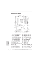 4
4 -
 5
5 -
 6
6 -
 7
7 -
8
-
9
-
10
-
11
-
12
-
13
-
14
-
15
-
16
-
17
-
18
-
19
-
20
-
21
-
22
-
23
-
24
-
25
-
26
-
27
-
28
-
29
-
30
-
31
-
32
-
33
-
34
-
35
-
36
-
37
-
38
-
39
-
40
-
41
-
42
-
43
-
44
-
45
-
46
-
47
-
48
-
49
-
50
-
51
-
52
-
53
-
54
-
55
-
56
-
57
-
58
-
59
-
60
-
61
-
62
-
63
-
64
-
65
-
66
-
67
-
68
-
69
-
70
-
71
-
72
-
73
-
74
-
75
-
76
-
77
-
78
-
79
-
80
-
81
-
82
-
83
-
84
-
85
-
86
-
87
-
88
-
89
-
90
-
91
-
92
-
93
-
94
-
95
-
96
-
97
-
98
-
99
-
100
-
101
-
102
-
103
-
104
-
105
-
106
-
107
-
108
-
109
-
110
-
111
-
112
-
113
-
114
-
115
-
116
-
117
-
118
-
119
-
120
-
121
-
122
-
123
-
124
-
125
-
126
-
127
-
128
-
129
-
130
-
131
-
132
-
133
-
134
-
135
-
136
-
137
-
138
-
139
-
140
-
141
-
142
-
143
-
144
-
145
-
146
-
147
-
148
-
149
-
150
-
151
-
152
-
153
-
154
-
155
-
156
-
157
-
158
-
159
-
160
-
161
-
162
-
163
-
164
-
165
-
166
-
167
-
168
-
169
-
170
-
171
-
172
-
173
-
174
-
175
-
176
-
177
-
178
-
179
-
180
-
181
-
182
-
183
-
184
-
185
-
186
-
187
-
188
-
189
-
190
-
191
-
192
-
193
-
194
-
195
-
196
-
197
-
198
-
199
-
200
-
201
-
202
-
203
-
204
-
205
-
206
-
207
-
208
-
209
-
210
-
211
-
212
-
213
-
214
-
215
-
216
-
217
-
218
-
219
-
220
-
221
-
222
-
223
-
224
-
225
-
226
-
227
-
228
-
229
-
230
-
231
-
232
-
233
-
234
-
235
-
236
-
237
-
238
-
239
-
240
-
241
-
242
-
243
-
244
-
245
-
246
-
247
-
248
-
249
-
250
-
251
-
252
-
253
-
254
-
255
-
256
-
257
-
258
-
259
-
260
-
261
-
262
-
263
-
264
-
265
-
266
 |
 |
Fatal1ty P67 Performance Series Motherboard
1
English
Who knew that at age 19, I would be a World Champion PC gamer. When I was 13, I
actually played competitive billiards in professional tournaments and won four or five
games off guys who played at the highest level. I actually thought of making a career
of it, but at that young age situations change rapidly. Because I’ve been blessed with
great hand-eye coordination and a grasp of mathematics (an important element in video
gaming) I gravitated to that activity.
GOING PRO
I started professional gaming in 1999 when I entered the CPL (Cyberathlete Professional
League) tournament in Dallas and won $4,000 for coming in third place. Emerging as one
of the top players in the United States, a company interested in sponsoring me
fl
ew me
to Sweden to compete against the top 12 players in the world. I won 18 straight games,
lost none, and took
fi
rst place, becoming the number one ranked Quake III player in the
world in the process. Two months later I followed that success by traveling to Dallas
and defending my title as the world’s best Quake III player, winning the $40,000 grand
prize. From there I entered competitions all over the world, including Singapore, Korea,
Germany, Australia, Holland and Brazil in addition to Los Angeles, New York and St.
Louis.
WINNING STREAK
I was excited to showcase my true gaming skills when defending my title as CPL
Champion of the year at the CPL Winter 2001 because I would be competing in a totally
different first person shooter (fps) game, Alien vs. Predator II. I won that competition
and walked away with a new car. The next year I won the same title playing Unreal
Tournament 2003, becoming the only three-time CPL champion of the year. And I did it
playing a different game each year, something no one else has ever done and a feat of
which I am extremely proud.
At QuakeCon 2002, I faced off against my rival ZeRo4 in one of the most highly
anticipated matches of the year, winning in a 14 to (-1) killer victory. Competing at
Quakecon 2004, I became the World’s 1st Doom3 Champion by defeating Daler in a
series of very challenging matches and earning $25,000 for the victory.
Since then Fatal1ty has traveled the globe to compete against the best in the world,
winning prizes and acclaim, including the 2005 CPL World Tour Championship in New
York City for a $150,000
fi
rst place triumph. In August 2007, Johnathan was awarded the
fi
rst ever Lifetime Achievement Award in the four year history of the eSports-Award for
“showing exceptional sportsmanship, taking part in shaping eSports into what it is today
and for being the prime representative of this young sport. He has become the
fi
gurehead
for eSports worldwide”.
Fatal1ty Story