ASRock Fatal1ty P67 Performance Quick Installation Guide - Page 49
oder den Line-in-Port Ihres PCs
 |
View all ASRock Fatal1ty P67 Performance manuals
Add to My Manuals
Save this manual to your list of manuals |
Page 49 highlights
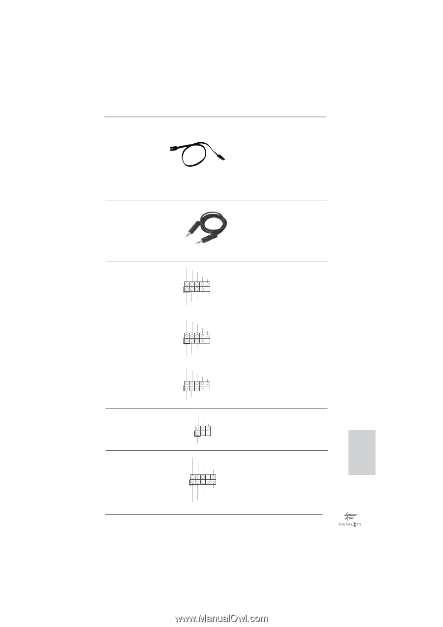
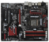
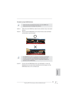
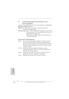
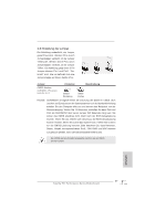
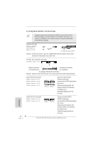
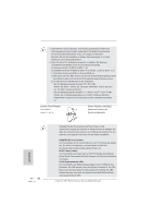
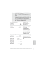
Serial ATA- (SATA-) Datenkabel (Option) SJedes Ende des SATA Datenkabels kann an die SATA / SATAII / SATA3 Festplatte oder das SATAII / SATA3 Verbindungsstück auf dieser Hauptplatine angeschlossen werden. Audiokabel (3,5 mm, Klinke) (Option) Beide Enden des 3,5-mm-Klin kenaudiokabels können an portable Audiogeräte, wie z. B. MP3-Player und Mobiltelefone, oder den Line-in-Port Ihres PCs angeschlossen werden. USB 2.0-Header (9-pol. USB8_9) (siehe S.4 - No. 27) (9-pol. USB10_11) (siehe S.4 - No. 26) (9-pol. USB12_13) (siehe S.4 - No. 25) USB_PWR P-9 P+9 GND DUMMY 1 GND P+8 P-8 USB_PWR USB_PWR P-11 P+11 GND DUMMY 1 GND P+10 P-10 USB_PWR USB_PWR P-13 P+13 GND DUMMY 1 GND P+12 P-12 USB_PWR Zusätzlich zu den sechs üblichen USB 2.0-Ports an den I/O-Anschlüssen befinden sich drei USB 2.0Anschlussleisten am Motherboard. Pro USB 2.0Anschlussleiste werden zwei USB 2.0-Ports unterstützt. Infrarot-Modul-Header (5-pin IR1) (siehe S.4 - No. 29) IRTX +5VSB DUMMY 1 GND IRRX Dieser Header unterstützt ein optionales, drahtloses Sendeund Empfangs-Infrarotmodul. Anschluss für Audio auf der Gehäusevorderseite (9-Pin HD_AUDIO1) GND PRESENCE# MIC_RET OUT_RET Dieses Interface zu einem Audio-Panel auf der Vorder seite Ihres Gehäuses, (siehe S.4 - No. 32) 1 OUT2_L J_SENSE OUT2_R MIC2_R MIC2_L ermöglicht Ihnen eine bequeme Anschlussmöglichkeit und Kontrolle über Audio-Geräte. 49 Fatal1ty P67 Performance Series Motherboard Deutsch
-
 1
1 -
2
-
3
-
4
-
5
-
6
-
7
-
8
-
9
-
10
-
11
-
12
-
13
-
14
-
15
-
16
-
17
-
18
-
19
-
20
-
21
-
22
-
23
-
24
-
25
-
26
-
27
-
28
-
29
-
30
-
31
-
32
-
33
-
34
-
35
-
36
-
37
-
38
-
39
-
40
-
41
-
42
-
43
-
 44
44 -
 45
45 -
 46
46 -
 47
47 -
 48
48 -
 49
49 -
 50
50 -
 51
51 -
 52
52 -
 53
53 -
 54
54 -
55
-
56
-
57
-
58
-
59
-
60
-
61
-
62
-
63
-
64
-
65
-
66
-
67
-
68
-
69
-
70
-
71
-
72
-
73
-
74
-
75
-
76
-
77
-
78
-
79
-
80
-
81
-
82
-
83
-
84
-
85
-
86
-
87
-
88
-
89
-
90
-
91
-
92
-
93
-
94
-
95
-
96
-
97
-
98
-
99
-
100
-
101
-
102
-
103
-
104
-
105
-
106
-
107
-
108
-
109
-
110
-
111
-
112
-
113
-
114
-
115
-
116
-
117
-
118
-
119
-
120
-
121
-
122
-
123
-
124
-
125
-
126
-
127
-
128
-
129
-
130
-
131
-
132
-
133
-
134
-
135
-
136
-
137
-
138
-
139
-
140
-
141
-
142
-
143
-
144
-
145
-
146
-
147
-
148
-
149
-
150
-
151
-
152
-
153
-
154
-
155
-
156
-
157
-
158
-
159
-
160
-
161
-
162
-
163
-
164
-
165
-
166
-
167
-
168
-
169
-
170
-
171
-
172
-
173
-
174
-
175
-
176
-
177
-
178
-
179
-
180
-
181
-
182
-
183
-
184
-
185
-
186
-
187
-
188
-
189
-
190
-
191
-
192
-
193
-
194
-
195
-
196
-
197
-
198
-
199
-
200
-
201
-
202
-
203
-
204
-
205
-
206
-
207
-
208
-
209
-
210
-
211
-
212
-
213
-
214
-
215
-
216
-
217
-
218
-
219
-
220
-
221
-
222
-
223
-
224
-
225
-
226
-
227
-
228
-
229
-
230
-
231
-
232
-
233
-
234
-
235
-
236
-
237
-
238
-
239
-
240
-
241
-
242
-
243
-
244
-
245
-
246
-
247
-
248
-
249
-
250
-
251
-
252
-
253
-
254
-
255
-
256
-
257
-
258
-
259
-
260
-
261
-
262
-
263
-
264
-
265
-
266
 |
 |