ASRock H110TM-ITX R2.0 User Manual
ASRock H110TM-ITX R2.0 Manual
 |
View all ASRock H110TM-ITX R2.0 manuals
Add to My Manuals
Save this manual to your list of manuals |
ASRock H110TM-ITX R2.0 manual content summary:
- ASRock H110TM-ITX R2.0 | User Manual - Page 1
- ASRock H110TM-ITX R2.0 | User Manual - Page 2
documentation are furnished for informational use only and subject to change without notice, and should not be constructed as a commitment by ASRock. ASRock assumes no responsibility for any errors or omissions that may appear in this documentation. With respect to the contents of this documentation - ASRock H110TM-ITX R2.0 | User Manual - Page 3
if the goods fail to be of acceptable quality and the failure does not amount to a major failure. If you require assistance please call ASRock Tel : +886-2-28965588 ext.123 (Standard International call charges apply) The terms HDMI™ and HDMI High-Definition Multimedia Interface, and the HDMI logo - ASRock H110TM-ITX R2.0 | User Manual - Page 4
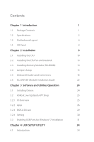
-DIMM) 14 2.4 Jumpers Setup 15 2.5 Onboard Headers and Connectors 16 2.6 M.2 WiFi/BT Module Installation Guide 22 Chapter 3 Software and Utilities Operation 24 3.1 Installing Drivers 24 3.2 ASRock Live Update & APP Shop 25 3.2.1 UI Overview 25 3.2.2 Apps 26 3.2.3 BIOS & Drivers 29 - ASRock H110TM-ITX R2.0 | User Manual - Page 5
4.2 EZ Mode 35 4.3 Advanced Mode 36 4.3.1 UEFI Menu Bar 36 4.3.2 Navigation Keys 37 4.4 Main Screen 38 4.5 OC Tweaker Screen 39 4.6 Advanced Screen 46 4.6.1 CPU Configuration 47 4.6.2 Chipset Configuration 49 4.6.3 Storage Configuration 51 4.6.4 Super IO Configuration 52 4.6.5 - ASRock H110TM-ITX R2.0 | User Manual - Page 6
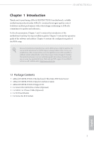
latest VGA cards and CPU support list on ASRock's website as well. ASRock website http://www.asrock.com. 1.1 Package Contents • ASRock H110TM-ITX R2.0 Motherboard (Thin Mini-ITX Form Factor) • ASRock H110TM-ITX R2.0 Quick Installation Guide • ASRock H110TM-ITX R2.0 Support CD • 2 x Serial ATA (SATA - ASRock H110TM-ITX R2.0 | User Manual - Page 7
(Compatible with Mini-ITX) • Solid Capacitor design • Supports 6th Generation Intel® CoreTM i7/i5/i3/Pentium®/ Celeron® Processors (Socket 1151) • Supports CPU up to 65W • Digi Power design • 5 Power Phase design • Supports Intel® Turbo Boost 2.0 Technology • Intel® H110 Memory • Dual Channel - ASRock H110TM-ITX R2.0 | User Manual - Page 8
H110TM-ITX R2.0 • Supports HDMI with max. resolution up to 4K x 2K (4096x2160) @ 24Hz / (3840x2160) @ 30Hz • Supports D-Sub with max. resolution up to 1920x1200 @ 60Hz • Supports DisplayPort 1.2 with max. resolution up to 4K x 2K (4096x2304) @ 60Hz • Supports LVDS with max. resolution up to - ASRock H110TM-ITX R2.0 | User Manual - Page 9
• 1 x Internal Power Header • 1 x SATA Power Connector • 3 x USB 2.0 Headers (Support 5 USB 2.0 ports) (Supports ESD Protection (ASRock Full Spike Protection)) • 1 x USB 3.0 Header (Supports 2 USB 3.0 ports) (Supports ESD Protection (ASRock Full Spike Protection)) * USB3_4_5 is shared with USB4_5 - ASRock H110TM-ITX R2.0 | User Manual - Page 10
H110TM-ITX R2.0 BIOS Feature • AMI UEFI Legal BIOS with multilingual GUI support • ACPI 5.0 Compliant wake up events • SMBIOS 2.7 Support to page 31 or more detailed instructions. * For the updated Windows® 10 driver, please visit ASRock's website for details: http://www.asrock.com • FCC, CE, WHQL - ASRock H110TM-ITX R2.0 | User Manual - Page 11
PNL_PWR1 DISPLAY1 M2_1 LVDS1 VGA1 CPU_FAN1 Intel DDR4_B1 DDR4_A1 H110 HDMI1 M2_2 RJ-45 LAN USB 2.0 T: USB0 B: USB1 Mic In HD_AUDIO1 1 1 Front HD_AUDIO2 Speaker SPEAKER1 1 HDMI_SPDIF1 1 1 BIOS ROM HTPC1 1 AUDIO CODEC RoHS DMIC1 H110TM-ITX 1 COM1 1 BLT_VOL1 USB2_3 1 English - ASRock H110TM-ITX R2.0 | User Manual - Page 12
(HD_AUDIO1) 23 Digital MIC Header (DMIC1) 24 SPDIF Out Connector (HDMI_SPDIF1) 25 3W Audio AMP Output Wafer Header (SPEAKER1) 26 Analog Surround Audio Header (HD_AUDIO2) H110TM-ITX R2.0 English 7 - ASRock H110TM-ITX R2.0 | User Manual - Page 13
HP-TBC-BA52-150W/19V FSP-FSP150-ABAN1-150W/19V FA130PE1-00-130W/19.5V LA90PE0-01-90W/19.5V This motherboard is available with support for either 2-pin ATX 19V power or DC-in power supplies. Please do not use two kinds of power supplies at the same time! Doing - ASRock H110TM-ITX R2.0 | User Manual - Page 14
H110TM-ITX R2.0 Chapter 2 Installation This is a Thin Mini-ITX form factor motherboard. Before you install the motherboard, study the configuration of your chassis to ensure that the motherboard fits into it. Pre-installation Precautions - ASRock H110TM-ITX R2.0 | User Manual - Page 15
2.1 Installing the CPU 1. Before you insert the 1151-Pin CPU into the socket, please check if the PnP cap is on the socket, if the CPU surface is unclean, or if there are any bent pins in the socket. Do not force to insert the CPU into the socket if above situation is found. Otherwise, the CPU will - ASRock H110TM-ITX R2.0 | User Manual - Page 16
H110TM-ITX R2.0 3 4 5 11 English - ASRock H110TM-ITX R2.0 | User Manual - Page 17
Please save and replace the cover if the processor is removed. The cover must be placed if you wish to return the motherboard for after service. 12 English - ASRock H110TM-ITX R2.0 | User Manual - Page 18
2.2 Installing the CPU Fan and Heatsink H110TM-ITX R2.0 1 2 CPU_FAN English 13 - ASRock H110TM-ITX R2.0 | User Manual - Page 19
2.3 Installing Memory Modules (SO-DIMM) This motherboard provides two 260-pin DDR4 (Double Data Rate 4) SO-DIMM slots. It is not allowed to install a DDR, DDR2 or DDR3 memory module into a DDR4 slot; otherwise, this motherboard and SO-DIMM may be damaged. The SO-DIMM only fits in one correct - ASRock H110TM-ITX R2.0 | User Manual - Page 20
H110TM-ITX R2.0 2.4 Jumpers Setup The illustration shows how jumpers are setup. When the jumper cap is placed on the pins, the jumper is "Short". If no jumper - ASRock H110TM-ITX R2.0 | User Manual - Page 21
wire assignments and the pin assignments are matched correctly. English Serial ATA3 Connectors (SATA3_0: see p.6, No. 7) (SATA3_1: see p.6, No. 8) SATA3_0 SATA3_1 These two SATA3 connectors support SATA data cables for internal storage devices with up to 6.0 Gb/s data transfer rate. 16 - ASRock H110TM-ITX R2.0 | User Manual - Page 22
H110TM-ITX R2.0 SATA Power Connector (SATA_POW1) (see p.6, No. 9) USB 2.0 Headers (5-pin USB6) (see p.6, No. 3) (9-pin on the I/O panel, there is one header on this motherboard. This USB 3.0 header can support two ports. * USB3_4_5 is shared with USB4_5. Front Panel Audio Header GN D (9-pin - ASRock H110TM-ITX R2.0 | User Manual - Page 23
Jack Sensing, but the panel wire on the chassis must support HDA to function correctly. Please follow the instructions in our manual and chassis manual to install your system. 2. If you use an AC'97 audio panel, please install it to the front panel audio header by the steps below: A. - ASRock H110TM-ITX R2.0 | User Manual - Page 24
H110TM-ITX R2.0 Chassis Fan Connector (4-pin CHA_FAN1) (see p.6, No. 6) FAN_SPEED_CONTROL COM1) (see p.6, No. 17) RI RTS GND TXD DCD 1 NC CTS DSR DTR RXD This header supports serial port modules. Backlight Control Header (8-pin BLT_VOL1) (see p.6, No. 16) 1 1: BKLT_EN 2: BKLT_PWM - ASRock H110TM-ITX R2.0 | User Manual - Page 25
English Digital MIC Header 1 (5-pin DMIC1) (see p.6, No. 23) Home Theater PC Header 1 (7-pin HTPC1) (see p.6, No. 21) LVDS Panel Connector 1 (40-pin LVDS1) (see p.6, No. 15) 40 20 1: +5V 2: No pin 3: SPDIF_OUT/DMIC_ CLK 4: GND 5: DMIC_DATA 6: +3.3V PIN Signal Name PIN Signal Name 8 - ASRock H110TM-ITX R2.0 | User Manual - Page 26
H110TM-ITX R2.0 PIN Signal Name PIN Signal Name LCD_VCC 18 38 (3.3V/5V/12V) BKLT_PWR (12V/19V) LCD_VCC 19 39 NC (3.3V/5V/12V) LCD_VCC 20 40 - ASRock H110TM-ITX R2.0 | User Manual - Page 27
2.6 M.2 WiFi/BT Module Installation Guide The M.2, also known as the Next Generation Form Factor (NGFF), is a small size and versatile card edge connector that aims to replace mPCIe and mSATA. The M.2 Socket (Key E) (M2_1) supports type 2230 WiFi/BT module. Installing the WiFi/BT module Step 1 - ASRock H110TM-ITX R2.0 | User Manual - Page 28
H110TM-ITX R2.0 Step 4 Tighten the screw with a screwdriver to secure the module into place. Please do not overtighten the screw as this might damage the module. A 23 English - ASRock H110TM-ITX R2.0 | User Manual - Page 29
CD that comes with the motherboard contains necessary drivers and useful utilities that enhance the motherboard's features. Running The Support CD To begin using the support CD, insert the CD into your CD-ROM drive. The CD automatically displays the Main Menu if "AUTORUN" is enabled in your computer - ASRock H110TM-ITX R2.0 | User Manual - Page 30
H110TM-ITX R2.0 3.2 ASRock Live Update & APP Shop The ASRock Live Update & APP Shop is an online store for purchasing and downloading software applications for your ASRock computer. You can quickly and easily install various apps and support utilities, such as USB Key, XFast LAN, XFast RAM and more - ASRock H110TM-ITX R2.0 | User Manual - Page 31
3.2.2 Apps When the "Apps" tab is selected, you will see all the available apps on screen for you to download. Installing an App Step 1 Find the app you want to install. The most recommended app appears on the left side of the screen. The other various apps are shown on the right. Please scroll up - ASRock H110TM-ITX R2.0 | User Manual - Page 32
H110TM-ITX R2.0 Step 3 If you want to install the app, click on the red icon to start downloading. Step 4 When installation completes, you can find the green " - ASRock H110TM-ITX R2.0 | User Manual - Page 33
Upgrading an App You can only upgrade the apps you have already installed. When there is an available new version for your app, you will find the mark of "New Version" appears below the installed app icon. Step 1 Click on the app icon to see more details. Step 2 Click on the yellow icon to start - ASRock H110TM-ITX R2.0 | User Manual - Page 34
H110TM-ITX R2.0 3.2.3 BIOS & Drivers Installing BIOS or Drivers When the "BIOS & Drivers" tab is selected, you will see a list of recommended or critical updates for the BIOS - ASRock H110TM-ITX R2.0 | User Manual - Page 35
3.2.4 Setting In the "Setting" page, you can change the language, select the server location, and determine if you want to automatically run the ASRock Live Update & APP Shop on Windows startup. 30 English - ASRock H110TM-ITX R2.0 | User Manual - Page 36
H110TM-ITX R2.0 3.3 Enabling USB Ports for Windows® 7 Installation Intel® Braswell and Skylake has removed their support for the Enhanced Host Controller Interface (EHCI - USB2.0) and only kept the eXtensible Host Controller Interface (XHCI - USB3.0). Due to that fact that XHCI is - ASRock H110TM-ITX R2.0 | User Manual - Page 37
Instructions Step 1 Insert the Windows® 7 installation disk or USB drive to your system. Step 2 Extract the tool (Win7 USB "USB Driver Folder" by clicking the red circle as shown as the picture below. If you are using ASRock's Support CD for the USB 3.0 driver, please select your CD-ROM. 32 English - ASRock H110TM-ITX R2.0 | User Manual - Page 38
H110TM-ITX R2.0 Step 5 Select where to save the ISO file by pressing the red circle as shown as the picture below. Step 6 If you want to burn - ASRock H110TM-ITX R2.0 | User Manual - Page 39
may run the UEFI SETUP UTILITY by pressing or right after you power on the computer, otherwise, the Power-On-Self-Test (POST) will continue with its test routines. If you wish to enter the UEFI SETUP UTILITY after POST, restart the system by pressing + + , or by - ASRock H110TM-ITX R2.0 | User Manual - Page 40
H110TM-ITX R2.0 4.2 EZ Mode The EZ Mode screen appears when you enter the BIOS setup program by default. EZ mode is a dashboard which contains multiple readings of - ASRock H110TM-ITX R2.0 | User Manual - Page 41
4.3 Advanced Mode The Advanced Mode provides more options to configure the BIOS settings. Refer to the following sections for the detailed configurations. To access the EZ Mode, press or click the "EZ Mode" button at the upper right corner of the screen. 4.3.1 UEFI Menu Bar The top of the - ASRock H110TM-ITX R2.0 | User Manual - Page 42
H110TM-ITX R2.0 4.3.2 Navigation Keys Use < > key or < > key to choose among the selections on the menu bar, and use < > key or < > key to move the cursor up - ASRock H110TM-ITX R2.0 | User Manual - Page 43
4.4 Main Screen When you enter the UEFI SETUP UTILITY, the Main screen will appear and display the system overview. My Favorite Display your collection of BIOS items. Press F5 to add/remove your favorite items. 38 English - ASRock H110TM-ITX R2.0 | User Manual - Page 44
features. H110TM-ITX R2.0 Because the UEFI software is constantly being updated, the following UEFI setup screens and descriptions are for reference purpose only, and they may not exactly match what you see on your screen. CPU Configuration Intel SpeedStep Technology Intel SpeedStep technology - ASRock H110TM-ITX R2.0 | User Manual - Page 45
DRAM Timing Configuration DRAM Reference Clock Select Auto for optimized settings. DRAM Frequency If [Auto] is selected, the motherboard will detect the memory module(s) inserted and assign the appropriate frequency automatically. Primary Timing CAS# Latency (tCL) The time between sending a column - ASRock H110TM-ITX R2.0 | User Manual - Page 46
H110TM-ITX R2.0 RAS to RAS Delay (tRRD_S) The number of clocks between two rows activated in different banks of the same rank. Write to Read Delay (tWTR_L) - ASRock H110TM-ITX R2.0 | User Manual - Page 47
tRDRD_dd Configure between module read to read delay. tRDWR_sg Configure between module read to write delay. tRDWR_dg Configure between module read to write delay. tRDWR_dr Configure between module read to write delay. tRDWR_dd Configure between module read to write delay. tWRRD_sg Configure between - ASRock H110TM-ITX R2.0 | User Manual - Page 48
twRPRE. Write_Early_ODT Configure Write_Early_ODT. tAONPD Configure tAONPD. tXP Configure tXP. tXPDLL Configure tXPDLL. tPRPDEN Configure tPRPDEN. tRDPDEN Configure tRDPDEN. twRPDEN Configure twRPDEN. OREF_RI Configure OREF_RI. H110TM-ITX R2.0 43 English - ASRock H110TM-ITX R2.0 | User Manual - Page 49
for channel A. ODT PARK (CH B) Configure the memory on die termination resistors' PARK for channel B. ODT NOM (CH A) Use this to change ODT (CH A) Auto/Manual settings. The default is [Auto]. ODT NOM (CH B) Use this to change ODT (CH B) Auto - ASRock H110TM-ITX R2.0 | User Manual - Page 50
H110TM-ITX R2.0 MRC Fast Boot Enable Memory Fast Boot to skip DRAM memory training for booting faster. Voltage Configuration DRAM Voltage Use this to configure DRAM Voltage. - ASRock H110TM-ITX R2.0 | User Manual - Page 51
4.6 Advanced Screen In this section, you may set the configurations for the following items: CPU Configuration, Chipset Configuration, Storage Configuration, Super IO Configuration, ACPI Configuration and USB Configuration. Setting wrong values in this section may cause the system to malfunction. - ASRock H110TM-ITX R2.0 | User Manual - Page 52
4.6.1 CPU Configuration H110TM-ITX R2.0 Intel Hyper Threading Technology Intel Hyper Threading Technology allows multiple threads to run on each core, so that the overall performance on threaded software is improved. Active Processor Cores Select - ASRock H110TM-ITX R2.0 | User Manual - Page 53
Automatically prefetch the subsequent cache line while retrieving the currently requested cache line. Enable for better performance. SW Guard Extensions (SGX) Intel SGX is a set of new CPU instructions that can be used by applications to set aside private regions of code and data. 48 English - ASRock H110TM-ITX R2.0 | User Manual - Page 54
H110TM-ITX R2.0 Top Of Lower Usable Dram Maximum Value of TOLUD. Dynamic assignment would adjust TOLUD automatically based on largest MMIO length of installed graphic controller. VT-d Intel DMI Link. PCH DMI ASPM Support This option enables/disables the ASPM support for all PCH DMI devices. IOAPIC - ASRock H110TM-ITX R2.0 | User Manual - Page 55
Share Memory Configure the size of memory that is allocated to the integrated graphics processor when the system boots up. Render Standby Power down the render unit when the GPU is idle for lower power consumption. Onboard LAN Enable or disable the onboard network interface controller. Onboard HD - ASRock H110TM-ITX R2.0 | User Manual - Page 56
4.6.3 Storage Configuration H110TM-ITX R2.0 SATA Controller(s) Enable/disable the SATA controllers. SATA Aggressive Link Power Management SATA Aggressive Link Power Management allows SATA devices to enter a low power state during periods of inactivity to save power. It is only supported by AHCI - ASRock H110TM-ITX R2.0 | User Manual - Page 57
4.6.4 Super IO Configuration Serial Port 1 Enable or disable the Serial port. Serial Port Address Select the address of the Serial port. 52 English - ASRock H110TM-ITX R2.0 | User Manual - Page 58
4.6.5 ACPI Configuration H110TM-ITX R2.0 Suspend to RAM Select disable for ACPI suspend type S1. It is recommended to select auto for ACPI S3 power saving. ACPI HEPT Table Enable - ASRock H110TM-ITX R2.0 | User Manual - Page 59
4.6.6 USB Configuration PS/2 Simulator Enable PS/2 Simulator. This should be enabled for the complete USB keyboard legacy support for non-USB aware OSes. *Enable this option if you install Windows 7. 54 English - ASRock H110TM-ITX R2.0 | User Manual - Page 60
4.7 Tools H110TM-ITX R2.0 OMG (Online Management Guard) ASRock Tech Service if you are having trouble with your PC. Please setup network configuration before using UEFI Tech Service. Easy Driver Installer For users that don't have an optical disk drive to install the drivers from our support - ASRock H110TM-ITX R2.0 | User Manual - Page 61
Flash Save UEFI files in your USB storage device and run Instant Flash to update your UEFI. Internet Flash - DHCP (Auto IP), Auto ASRock Internet Flash downloads and updates the latest UEFI firmware version from our servers for you. Please setup network configuration before using Internet Flash - ASRock H110TM-ITX R2.0 | User Manual - Page 62
Network Configuration Use this to configure internet connection settings for Internet Flash. H110TM-ITX R2.0 Internet Setting Enable or disable sound effects in the setup utility. UEFI Download Server Select a server to download the UEFI firmware. English 57 - ASRock H110TM-ITX R2.0 | User Manual - Page 63
4.8 Hardware Health Event Monitoring Screen This section allows you to monitor the status of the hardware on your system, including the parameters of the CPU temperature, motherboard temperature, fan speed and voltage. Fan-Tastic Tuning Select a fan mode for CPU Fan 1, or choose Customize to set 5 - ASRock H110TM-ITX R2.0 | User Manual - Page 64
H110TM-ITX R2.0 4.9 Security Screen In this section you may set or change the remove the password. Secure Boot Use this item to enable or disable support for Windows 8.1 Secure Boot. Intel(R) Platform Trust Technology Enable/disable Intel PTT in ME. Disable this option to use discrete TPM Module. - ASRock H110TM-ITX R2.0 | User Manual - Page 65
minimizes your computer's boot time. In fast mode you may not boot from an USB storage device. Ultra Fast mode is only supported by Windows 8.1 and the VBIOS must support UEFI GOP if you are using an external graphics card. Please notice that Ultra Fast mode will boot so fast that the - ASRock H110TM-ITX R2.0 | User Manual - Page 66
H110TM-ITX R2.0 Full Screen Logo Enable to display the boot logo or disable to show normal POST messages. AddOn ROM Display Enable AddOn ROM Display to see - ASRock H110TM-ITX R2.0 | User Manual - Page 67
do not disable unless you're running a WHCK test. If you are using Windows 8.1 64-bit and all of your devices support UEFI, you may also disable CSM for faster boot speed. Launch PXE OpROM Policy Select UEFI only to run those that support UEFI option ROM only. Select Legacy only to run - ASRock H110TM-ITX R2.0 | User Manual - Page 68
4.11 Exit Screen H110TM-ITX R2.0 Save Changes and Exit When you select this option the following message, "Save configuration changes and exit setup?" will pop out. Select [OK] to save - ASRock H110TM-ITX R2.0 | User Manual - Page 69
or want to know more about ASRock, you're welcome to visit ASRock's website at http://www.asrock.com; or you may contact your dealer for further information. For technical questions, please submit a support request form at http://www.asrock.com/support/tsd.asp ASRock Incorporation 2F., No.37, Sec
-
 1
1 -
 2
2 -
 3
3 -
 4
4 -
 5
5 -
 6
6 -
 7
7 -
8
-
9
-
10
-
11
-
12
-
13
-
14
-
15
-
16
-
17
-
18
-
19
-
20
-
21
-
22
-
23
-
24
-
25
-
26
-
27
-
28
-
29
-
30
-
31
-
32
-
33
-
34
-
35
-
36
-
37
-
38
-
39
-
40
-
41
-
42
-
43
-
44
-
45
-
46
-
47
-
48
-
49
-
50
-
51
-
52
-
53
-
54
-
55
-
56
-
57
-
58
-
59
-
60
-
61
-
62
-
63
-
64
-
65
-
66
-
67
-
68
-
69
 |
 |