ASRock H170 Combo User Manual
ASRock H170 Combo Manual
 |
View all ASRock H170 Combo manuals
Add to My Manuals
Save this manual to your list of manuals |
ASRock H170 Combo manual content summary:
- ASRock H170 Combo | User Manual - Page 1
- ASRock H170 Combo | User Manual - Page 2
documentation are furnished for informational use only and subject to change without notice, and should not be constructed as a commitment by ASRock. ASRock assumes no responsibility for any errors or omissions that may appear in this documentation. With respect to the contents of this documentation - ASRock H170 Combo | User Manual - Page 3
he terms HDMI™ and HDMI High-Deinition Multimedia Interface, and the HDMI logo are trademarks or registered trademarks of HDMI Licensing LLC in the United States and other countries. - ASRock H170 Combo | User Manual - Page 4
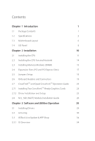
Installing Two CrossFireXTM-Ready Graphics Cards 23 2.7.2 Driver Installation and Setup 25 2.8 M.2_SSD (NGFF) Module Installation Guide 26 Chapter 3 Software and Utilities Operation 29 3.1 Installing Drivers 29 3.2 A-Tuning 30 3.3 ASRock Live Update & APP Shop 34 3.3.1 UI Overview 34 - ASRock H170 Combo | User Manual - Page 5
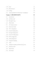
3.3.2 Apps 35 3.3.3 BIOS & Drivers 38 3.3.4 Setting 39 3.4 Enabling USB Ports for Windows® 7 Installation 40 Chapter 4 UEFI SETUP UTILITY 43 4.1 Introduction 43 4.1.1 UEFI Menu Bar 43 4.1.2 Navigation Keys 44 4.2 Main Screen 45 4.3 OC Tweaker Screen 46 4.4 Advanced Screen 54 - ASRock H170 Combo | User Manual - Page 6
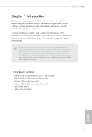
may ind the latest VGA cards and CPU support list on ASRock's website as well. ASRock website http://www.asrock.com. 1.1 Package Contents • ASRock H170 Combo Motherboard (ATX Form Factor) • ASRock H170 Combo Quick Installation Guide • ASRock H170 Combo Support CD • 2 x Serial ATA (SATA) Data Cables - ASRock H170 Combo | User Manual - Page 7
10 Power Phase design • Supports Intel® Turbo Boost 2.0 Technology Chipset • Intel® H170 • Supports Intel® Small Business Advantage 4.0 modules up to 1333 * Please refer to Memory Support List on ASRock's website for more information. (http://www.asrock.com/) • Max. capacity of system memory: - ASRock H170 Combo | User Manual - Page 8
H170 Combo Graphics Audio LAN • Intel® HD Graphics Built-in Visuals and the VGA outputs can be supported only with processors which are GPU integrated. • Supports ALC892 Audio Codec) • Premium Blu-ray Audio support • Supports Surge Protection (ASRock Full Spike Protection) • ELNA Audio Caps • Gigabit - ASRock H170 Combo | User Manual - Page 9
Power Connector • 1 x Front Panel Audio Connector • 2 x USB 2.0 Headers (Support 4 USB 2.0 ports) (Supports ESD Protection (ASRock Full Spike Protection)) • 1 x USB 3.0 Header (Supports 2 USB 3.0 ports) (Supports ESD Protection (ASRock Full Spike Protection)) BIOS Feature • 128Mb AMI UEFI Legal - ASRock H170 Combo | User Manual - Page 10
H170 Combo Hardware Monitor OS Certiications • SMBIOS 2.3.1 Support • CPU, GT_CPU, DRAM, VPPM, PCH 1.0V, VCCIO, VC- Please refer to page 40 for more detailed instructions. * For the updated Windows® 10 driver, please visit ASRock's website for details: http://www.asrock.com • FCC, CE, WHQL • ErP/ - ASRock H170 Combo | User Manual - Page 11
REAR SPK Bottom: CTR BASS USB_5_6 Top: LINE IN Center: FRONT Bottom: MIC IN CMOS 6 25 CPU_FAN1 CPU_FAN2 Battery PCI Express 3.0 PCIE1 H170 Combo PCIE2 LAN 1 Front USB 3.0 7 CHA_FAN2 8 9 SATA3_2 SATA3_0 M2_1 CT25 CT24 CT23 CT22 CT21 10 11 SATA3_3 SATA3_1 PCIE3 Audio CODEC - ASRock H170 Combo | User Manual - Page 12
) 22 TPM Header (TPMS1) 23 COM Port Header (COM1) 24 Front Panel Audio Header (HD_AUDIO1) 25 CPU Fan Connector (CPU_FAN1) 26 CPU Fan Connector (CPU_FAN2) H170 Combo English 7 - ASRock H170 Combo | User Manual - Page 13
1.4 I/O Panel 1 3 5 2 4 6 13 12 11 10 9 8 7 No. Description 1 PS/2 Mouse/Keyboard Port 2 LAN RJ-45 Port* 3 Side Speaker (Gray) 4 Rear Speaker (Black) 5 Line In (Light Blue) 6 Front Speaker (Lime)** 7 Microphone (Pink) No. Description 8 Central / Bass (Orange) 9 USB 3.0 Ports (USB_78) - ASRock H170 Combo | User Manual - Page 14
H170 Combo * here are two LEDs on each LAN port. Please refer to the table below for the LAN port LED indications. ACT/LINK LED SPEED LED - ASRock H170 Combo | User Manual - Page 15
Chapter 2 Installation his is an ATX form factor motherboard. Before you install the motherboard, study the coniguration of your chassis to ensure that the motherboard its into it. Pre-installation Precautions Take note of the following precautions before you install motherboard components or change - ASRock H170 Combo | User Manual - Page 16
H170 Combo 2.1 Installing the CPU 1. Before you insert the 1151-Pin CPU into the socket, please check if the PnP cap is on the socket, if the - ASRock H170 Combo | User Manual - Page 17
4 5 12 3 English - ASRock H170 Combo | User Manual - Page 18
H170 Combo Please save and replace the cover if the processor is removed. he cover must be placed if you wish to return the motherboard for ater service. 13 English - ASRock H170 Combo | User Manual - Page 19
2.2 Installing the CPU Fan and Heatsink 1 2 CPU_FAN English 14 - ASRock H170 Combo | User Manual - Page 20
H170 Combo 2.3 Installing Memory Modules (DIMM) his motherboard provides two 288-pin DDR4 (Double Data Rate 4) and four 240pin DDR3/DDR3L (Double Data Rate 3) DIMM slots, and supports Dual Channel Memory Technology. Warning! It is NOT allowed to install a memory module into a DDR4 slot and a DDR3 - ASRock H170 Combo | User Manual - Page 21
1 2 3 16 English - ASRock H170 Combo | User Manual - Page 22
H170 Combo 2.4 Expansion Slots (PCI and PCI Express Slots) here are 2 PCI slots and 4 PCI Express slots on the motherboard. Before installing an expansion card, please make - ASRock H170 Combo | User Manual - Page 23
2.5 Jumpers Setup he illustration shows how jumpers are setup. When the jumper cap is placed on the pins, the jumper is "Short". If no jumper cap is placed on the pins, the jumper is "Open". he illustration shows a 3-pin jumper whose pin1 and pin2 are "Short" when a jumper cap is placed on these 2 - ASRock H170 Combo | User Manual - Page 24
H170 Combo 2.6 Onboard Headers and Connectors Onboard headers and connectors are NOT jumpers. Do NOT place jumper caps over these headers and connectors. Placing jumper caps over - ASRock H170 Combo | User Manual - Page 25
Please connect the chassis power LED and the chassis speaker to this header. SATA3_3 SATA3_2 SATA3_1 SATA3_0 SATA3_5 SATA3_4 hese six SATA3 connectors support SATA data cables for internal storage devices with up to 6.0 Gb/s data transfer rate. he SATA3_0, SATA3_1 are shared with the SATA_E_1 - ASRock H170 Combo | User Manual - Page 26
H170 Combo USB 3.0 Headers (19-pin USB_5_6) (see p.6, No. 6) Vbus IntA_PA_SSRXIntA_PA_SSRX+ High Deinition Audio supports Jack Sensing, but the panel wire on the chassis must support HDA to function correctly. Please follow the instructions in our manual and chassis manual to install your system - ASRock H170 Combo | User Manual - Page 27
plug it along Pin 1 and Pin 5. RRXD1 DDTR#1 DDSR#1 CCTS#1 1 RRI#1 RRTS#1 GND TTXD1 DDCD#1 his COM1 header supports a serial port module. his connector supports Trusted Platform Module (TPM) system, 1 which can securely store keys, digital certiicates, passwords, and data. A TPM system also - ASRock H170 Combo | User Manual - Page 28
H170 Combo 2.7 CrossFireXTM and Quad CrossFireXTM Operation Guide his motherboard supports CrossFireXTM and Quad CrossFireXTM that allows to enable CrossFireXTM. Please refer to AMD graphics card manuals for detailed installation guide. 2.7.1 Installing Two CrossFireXTM-Ready Graphics Cards Step 1 - ASRock H170 Combo | User Manual - Page 29
Step 3 Connect a VGA cable or a DVI cable to the monitor connector or the DVI connector of the graphics card that is inserted to PCIE2 slot. 24 English - ASRock H170 Combo | User Manual - Page 30
H170 Combo 2.7.2 Driver Installation and Setup Step 1 Power on your computer and boot into OS. Step 2 Remove the AMD drivers if you have any VGA drivers installed - ASRock H170 Combo | User Manual - Page 31
2.8 M.2_SSD (NGFF) Module Installation Guide The M.2, also known as the Next Generation Form Factor (NGFF), is a small size and versatile card edge connector that aims to replace mPCIe and mSATA. The Ultra M.2 Sockets support M.2 PCI Express module up to Gen3 x4 (32 Gb/s). * If M2_1 is occupied by a - ASRock H170 Combo | User Manual - Page 32
E D C B A E D C B A C B A E D C B A H170 Combo Step 3 Move the standof based on the module type and length. he standof is placed at the nut location D by default. Skip Step 3 and 4 and - ASRock H170 Combo | User Manual - Page 33
the screw as this might damage the module. M.2_SSD (NGFF) Module Support List Vendor ADATA ADATA ADATA Crucial Crucial Intel Kingston Kingston Plextor Plextor Samsung Samsung updates of M.2_SSD (NFGG) module support list, please visit our website for details: http://www.asrock.com English 28 - ASRock H170 Combo | User Manual - Page 34
H170 Combo Chapter 3 Software and Utilities Operation 3.1 Installing Drivers he Support CD that comes with the motherboard contains necessary drivers and useful utilities that enhance the motherboard's features. Running The Support CD To begin using the support CD, insert the CD into your CD-ROM - ASRock H170 Combo | User Manual - Page 35
new features and improved utilities. 3.2.1 Installing A-Tuning A-Tuning can be downloaded from ASRock Live Update & APP Shop. Ater the installation, you will ind the icon System Info, FAN-Tastic Tuning, Tech Service and Settings. Operation Mode Choose an operation mode for your computer. 30 English - ASRock H170 Combo | User Manual - Page 36
OC Tweaker Conigurations for overclocking the system. H170 Combo System Info View information about the system. *he System Browser tab may not appear for certain models. 31 English - ASRock H170 Combo | User Manual - Page 37
to ive diferent fan speeds using the graph. he fans will automatically shit to the next speed level when the assigned temperature is met. Tech Service Contact Tech Service if you have problems with your computer. Please leave your contact information along with details of the - ASRock H170 Combo | User Manual - Page 38
H170 Combo Settings Conigure ASRock A-Tuning. Click to select "Auto run at Windows Startup" if you want A-Tuning to be launched when you start up the Windows operating system. 33 English - ASRock H170 Combo | User Manual - Page 39
Shop is an online store for purchasing and downloading sotware applications for your ASRock computer. You can quickly and easily install various apps and support utilities, such as USB Key, XFast LAN, XFast RAM and more. With ASRock APP Shop, you can optimize your system and keep your motherboard up - ASRock H170 Combo | User Manual - Page 40
H170 Combo 3.3.2 Apps When the "Apps" tab is selected, you will see all the available apps on screen for you to download. Installing an App Step 1 Find - ASRock H170 Combo | User Manual - Page 41
Step 3 If you want to install the app, click on the red icon to start downloading. Step 4 When installation completes, you can ind the green "Installed" icon appears on the upper right corner. English To uninstall it, simply click on the trash can icon . *he trash icon may not appear for certain - ASRock H170 Combo | User Manual - Page 42
H170 Combo Upgrading an App You can only upgrade the apps you have already installed. When there is an available new version for your app, you will - ASRock H170 Combo | User Manual - Page 43
3.3.3 BIOS & Drivers Installing BIOS or Drivers When the "BIOS & Drivers" tab is selected, you will see a list of recommended or critical updates for the BIOS or drivers. Please update them all soon. Step 1 Please check the item information before update. Click on Step 2 to see more details. - ASRock H170 Combo | User Manual - Page 44
H170 Combo 3.3.4 Setting In the "Setting" page, you can change the language, select the server location, and determine if you want to automatically run the ASRock Live Update & APP Shop on Windows startup. 39 English - ASRock H170 Combo | User Manual - Page 45
) • A Windows® PC • Win7 USB Patcher (included in the ASRock Support CD or website) Scenarios You have an ODD and PS/2 ports: If there is an optical disc drive, PS/2 ports and PS/2 Keyboard or mouse on your computer, you can skip the instructions below and go ahead to install Windows® 7 OS. You only - ASRock H170 Combo | User Manual - Page 46
H170 Combo Instructions Step 1 Insert the Windows® 7 installation disk or USB drive to your system. Step 2 Extract the tool (Win7 Folder" by clicking the red circle as shown as the picture below. If you are using ASRock's Support CD for the USB 3.0 driver, please select your CD-ROM. 41 English - ASRock H170 Combo | User Manual - Page 47
Step 5 Select where to save the ISO ile by pressing the red circle as shown as the picture below. Step 6 If you want to burn the patched image to a CD, please check "Burn Image" and select "Target Device to Burn". If not, the patched ISO image will be exported to the destination selected in Step5. - ASRock H170 Combo | User Manual - Page 48
H170 Combo Chapter 4 UEFI SETUP UTILITY 4.1 Introduction his section explains how to use the UEFI SETUP UTILITY to conigure your system. You may run the UEFI SETUP - ASRock H170 Combo | User Manual - Page 49
4.1.2 Navigation Keys Use < > key or < > key to choose among the selections on the menu bar, and use < > key or < > key to move the cursor up or down to select items, then press to get into the sub screen. You can also use the mouse to click your required item. Please check the following - ASRock H170 Combo | User Manual - Page 50
H170 Combo 4.2 Main Screen When you enter the UEFI SETUP UTILITY, the Main screen will appear and display the system overview. Favorite Display your collection of BIOS items. Press F5 to add/remove your favorite items. 45 English - ASRock H170 Combo | User Manual - Page 51
4.3 OC Tweaker Screen In the OC Tweaker screen, you can set up overclocking features. Because the UEFI sotware is constantly being updated, the following UEFI setup screens and descriptions are for reference purpose only, and they may not exactly match what you see on your screen. CPU Coniguration - ASRock H170 Combo | User Manual - Page 52
H170 Combo Long Duration Maintained Conigure the period of time until the CPU ratio is lowered when the Long Duration Power Limit is exceeded. Short Duration Power - ASRock H170 Combo | User Manual - Page 53
RAS# Active Time (tRAS) he number of clock cycles required between a bank active command and issuing the precharge command. Command Rate (CR) he delay between when a memory chip is selected and when the irst active command can be issued. Secondary Timing Write Recovery Time (tWR) he amount of delay - ASRock H170 Combo | User Manual - Page 54
H170 Combo CAS Write Latency (tCWL) Conigure CAS Write Latency. Third Timing tREFI Conigure refresh cycles at an average periodic interval. tCKE Conigure the period of time - ASRock H170 Combo | User Manual - Page 55
tWRRD_dr Conigure between module write to read delay. tWRRD_dd Conigure between module write to read delay. tWRWR_sg Conigure between module write to write delay. tWRWR_dg Conigure between module write to write delay. tWRWR_dr Conigure between module write to write delay. tWRWR_dd Conigure between - ASRock H170 Combo | User Manual - Page 56
twRPDEN. OREF_RI Conigure OREF_RI. tREFIx9 Conigure tREFIx9. txSDLL Conigure txSDLL. txs_ofset Conigure txs_ofset. tZQOPER Conigure tZQOPER. tMOD Conigure tMOD. ZQCS_period Conigure ZQCS_period. tZQCS Conigure tZQCS. H170 Combo 51 English - ASRock H170 Combo | User Manual - Page 57
on die termination resistors' PARK for channel B. ODT NOM (CH A) Use this to change ODT (CH A) Auto/Manual settings. he default is [Auto]. ODT NOM (CH B) Use this to change ODT (CH B) Auto/Manual settings. he default is [Auto]. MRC Fast Boot Enable Memory Fast Boot to skip DRAM memory training for - ASRock H170 Combo | User Manual - Page 58
VCCSA. Save User Default Type a proile name and press enter to save your settings as user default. Load User Default Load previously saved user defaults. H170 Combo English 53 - ASRock H170 Combo | User Manual - Page 59
UEFI setup utility. Full HD UEFI When [Auto] is selected, the resolution will be set to 1920 x 1080 if the monitor supports Full HD resolution. If the monitor does not support Full HD resolution, then the resolution will be set to 1024 x 768. When [Disable] is selected, the resolution will be set - ASRock H170 Combo | User Manual - Page 60
4.4.1 CPU Coniguration H170 Combo Active Processor Cores Select the number of cores to enable in each processor package. CPU C States Support Enable CPU C States Support for power saving. It is recommended to keep C3, C6 and C7 all enabled for better power saving. Enhanced Halt State (C1E) Enable - ASRock H170 Combo | User Manual - Page 61
Intel Virtualization Technology Intel Virtualization Technology allows a platform to run multiple operating systems and applications in independent partitions, so that one computer system can function as multiple virtual systems. Hardware Prefetcher Automatically prefetch data and code for the - ASRock H170 Combo | User Manual - Page 62
4.4.2 Chipset Coniguration H170 Combo Primary Graphics Adapter Select a primary VGA. Top of Lower Usable DRAM Set the link speed for PCIE2. PCIE4 Link Speed Select the link speed for PCIE4. PCIE ASPM Support his option enables/disables the ASPM support for all CPU downstream devices. 57 English - ASRock H170 Combo | User Manual - Page 63
his option enables/disables the control of ASPM on CPU side of the DMI Link. PCH DMI ASPM Support his option enables/disables the ASPM support for all PCH DMI devices. Share Memory Conigure the size of memory that is allocated to the integrated graphics processor when the system boots up. - ASRock H170 Combo | User Manual - Page 64
H170 Combo Good Night LED By enabling Good Night LED, the Power/HDD LEDs will be switched of when the system is on. It will also automatically switch of the Power and Keyboard LEDs when the system enters into Standby/Hibernation mode. 59 English - ASRock H170 Combo | User Manual - Page 65
drives into a logical unit. AHCI (Advanced Host Controller Interface) supports NCQ and other new features that will improve SATA disk performance power state during periods of inactivity to save power. It is only supported by AHCI mode. Hard Disk S.M.A.R.T. S.M.A.R.T stands for Self-Monitoring, - ASRock H170 Combo | User Manual - Page 66
4.4.4 Super IO Coniguration H170 Combo Serial Port Enable or disable the Serial port. Serial Port Address Select the address of the Serial port. PS2 Y-Cable Enable the PS2 Y-Cable or set this option to Auto. 61 English - ASRock H170 Combo | User Manual - Page 67
4.4.5 ACPI Coniguration Suspend to RAM Select disable for ACPI suspend type S1. It is recommended to select auto for ACPI S3 power saving. ACPI HEPT Table Enable the High Precision Event Timer for better performance. PS/2 Keyboard Power On Allow the system to be waked up by a PS/2 Keyboard. PCIE - ASRock H170 Combo | User Manual - Page 68
4.4.6 USB Coniguration H170 Combo Legacy USB Support Enable or disable Legacy OS Support for USB 2.0 devices. If you encounter USB compatibility issues it is recommended to disable legacy USB support. Select UEFI Setup Only to support USB devices under the UEFI setup and Windows/Linux operating - ASRock H170 Combo | User Manual - Page 69
4.4.7 Trusted Computing Security Device Support Enable or disable BIOS support for security device. 64 English - ASRock H170 Combo | User Manual - Page 70
4.5 Tools H170 Combo OMG (Online Management Guard) Administrators Service Contact ASRock Tech Service if you are having trouble with your PC. Please setup network coniguration before using UEFI Tech Service. Easy RAID Installer Easy RAID Installer helps you to copy the RAID driver from the support - ASRock H170 Combo | User Manual - Page 71
Boot Manager Boot Manager is speciically designed for the dual OS platform/multi-OS platform users to easily customize and manage the boot menu. *Please connect more than one boot devices to use this tool. Boot Manager Enable/disable the Boot Manager. Boot Manager Timeout Enable/disable the Boot - ASRock H170 Combo | User Manual - Page 72
H170 Combo Dehumidiier Duration Conigure the duration of the dehumidifying process before it device and run Instant Flash to update your UEFI. Internet Flash - DHCP (Auto IP), Auto ASRock Internet Flash downloads and updates the latest UEFI irmware version from our servers for you. Please setup - ASRock H170 Combo | User Manual - Page 73
Internet Setting Enable or disable sound efects in the setup utility. UEFI Download Server Select a server to download the UEFI irmware. 68 English - ASRock H170 Combo | User Manual - Page 74
H170 Combo 4.6 Hardware Health Event Monitoring Screen his section allows you to monitor the status of the hardware on your system, including the parameters of the CPU - ASRock H170 Combo | User Manual - Page 75
in the UEFI Setup Utility. Leave it blank and press enter to remove the password. Secure Boot Use this item to enable or disable support for Windows 8.1 Secure Boot. Intel(R) Platform Trust Technology Enable/disable Intel PTT in ME. Disable this option to use discrete TPM Module. 70 English - ASRock H170 Combo | User Manual - Page 76
H170 Combo 4.8 Boot Screen his section displays the available devices on your system for you to conigure the boot settings and the boot priority. Fast Boot Fast Boot minimizes your computer's boot time. In fast mode you may not boot from an USB storage device. Ultra Fast mode is only supported by - ASRock H170 Combo | User Manual - Page 77
Full Screen Logo Enable to display the boot logo or disable to show normal POST messages. AddOn ROM Display Enable AddOn ROM Display to see the AddOn ROM messages or conigure the AddOn ROM if you've enabled Full Screen Logo. Disable for faster boot speed. Boot Failure Message If the computer fails - ASRock H170 Combo | User Manual - Page 78
CSM (Compatibility Support Module) H170 Combo CSM Enable to launch the Compatibility Support Module. Please do not disable unless you're running a WHCK test. If you are using Windows 8.1 64-bit and all of your devices support UEFI, you may also disable CSM for faster boot speed. Launch PXE OpROM - ASRock H170 Combo | User Manual - Page 79
4.9 Exit Screen Save Changes and Exit When you select this option the following message, "Save coniguration changes and exit setup?" will pop out. Select [OK] to save changes and exit the UEFI SETUP UTILITY. Discard Changes and Exit When you select this option the following message, "Discard changes - ASRock H170 Combo | User Manual - Page 80
or want to know more about ASRock, you're welcome to visit ASRock's website at http://www.asrock.com; or you may contact your dealer for further information. For technical questions, please submit a support request form at http://www.asrock.com/support/tsd.asp ASRock Incorporation 2F., No.37, Sec
-
 1
1 -
 2
2 -
 3
3 -
 4
4 -
 5
5 -
 6
6 -
 7
7 -
8
-
9
-
10
-
11
-
12
-
13
-
14
-
15
-
16
-
17
-
18
-
19
-
20
-
21
-
22
-
23
-
24
-
25
-
26
-
27
-
28
-
29
-
30
-
31
-
32
-
33
-
34
-
35
-
36
-
37
-
38
-
39
-
40
-
41
-
42
-
43
-
44
-
45
-
46
-
47
-
48
-
49
-
50
-
51
-
52
-
53
-
54
-
55
-
56
-
57
-
58
-
59
-
60
-
61
-
62
-
63
-
64
-
65
-
66
-
67
-
68
-
69
-
70
-
71
-
72
-
73
-
74
-
75
-
76
-
77
-
78
-
79
-
80
 |
 |