ASRock H55 Pro Quick Installation Guide
ASRock H55 Pro Manual
 |
View all ASRock H55 Pro manuals
Add to My Manuals
Save this manual to your list of manuals |
ASRock H55 Pro manual content summary:
- ASRock H55 Pro | Quick Installation Guide - Page 1
for backup purpose, without written consent of ASRock Inc. Products and corporate names appearing in this guide may or may not be registered trademarks or ASRock Website: http://www.asrock.com Published December 2009 Copyright©2009 ASRock INC. All rights reserved. 1 ASRock H55 Pro Motherboard - ASRock H55 Pro | Quick Installation Guide - Page 2
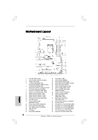
Motherboard Layout English 1 PS2_USB_PWR1 Jumper 2 ATX 12V Power Connector (ATX12V1) 3 1156-Pin CPU Socket Fan Connector (CHA_FAN3) 13 Intel H55 Chipset 14 Chassis Speaker Header ( ) 32 Front Panel Audio Header (HD_AUDIO1, Lime) 33 Internal Audio Connector: CD1 (Black ASRock H55 Pro Motherboard - ASRock H55 Pro | Quick Installation Guide - Page 3
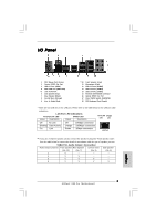
accordance with the type of speaker you use. TABLE for Audio Output Connection Audio Output Channels Front Speaker Rear Speaker Central / Bass Side Speaker (No. 10) (No. 7) (No. 8) (No. 6) 2 V -- -- -- 4 V V -- -- 6 V V V -- 8 V V V V 3 ASRock H55 Pro Motherboard English - ASRock H55 Pro | Quick Installation Guide - Page 4
. For Windows® 7 / 7 64-bit / VistaTM / VistaTM 64-bit OS: Please click "VIA HD Audio Deck" icon , and click "Advanced Options" on the left side on the bottom. In "Advanced Options" screen, select "Independent Headphone", and click "OK" to save your change. English 4 ASRock H55 Pro Motherboard - ASRock H55 Pro | Quick Installation Guide - Page 5
introduction of the motherboard and step-by-step installation guide. More detailed information of the motherboard can be found in the user manual presented in the Support CD. Because the motherboard specifications and the BIOS software might be updated, the content of this manual will be subject - ASRock H55 Pro | Quick Installation Guide - Page 6
Processors in LGA1156 Package - Advanced V8 + 2 Power Phase Design - Supports Intel® Turbo Boost Technology - Supports Hyper-Threading Technology (see CAUTION 1) - Supports Untied Overclocking Technology (see CAUTION 2) - Supports EM64T CPU - Intel® H55 with LED ASRock H55 Pro Motherboard English - ASRock H55 Pro | Quick Installation Guide - Page 7
PCH PLL Voltage Multi-adjustment - Supports I. O. T. (Intelligent Overclocking Technology) - Drivers, Utilities, AntiVirus Software (Trial Version), ASRock Software Suite (CyberLink DVD Suite and Creative Sound Blaster X-Fi MB) (OEM and Trial Version) - ASRock OC Tuner (see CAUTION 10) - Intelligent - ASRock H55 Pro | Quick Installation Guide - Page 8
, CrossFireXTM function will not work. 7. For microphone input, this motherboard supports both stereo and mono modes. For audio output, this motherboard supports 2-channel, 4-channel, 6-channel, and 8-channel modes. Please check the table on page 3 for proper connection. 8 ASRock H55 Pro Motherboard - ASRock H55 Pro | Quick Installation Guide - Page 9
operation procedures of Intelligent Energy Saver. ASRock website: http://www.asrock.com/feature/IES/index.html 12. ASRock Instant Flash is a BIOS flash utility embedded in Flash ROM. This convenient BIOS update tool allows you to update system BIOS without entering operating systems first like MS - ASRock H55 Pro | Quick Installation Guide - Page 10
with * mark are supported under Windows® VistaTM / VistaTM 64-bit only. * For the latest updates of the supported PCI Express VGA card list for CrossFireXTM Mode, please visit our website for details. ASRock website: http://www.asrock.com/support/index.htm English 10 ASRock H55 Pro Motherboard - ASRock H55 Pro | Quick Installation Guide - Page 11
Before you insert the 1156-Pin CPU into the socket, please check if the CPU surface is unclean or if there is any bent pin on the socket. Do not force to insert the CPU into the socket if above situation is found. Otherwise, the CPU will be seriously damaged. English 11 ASRock H55 Pro Motherboard - ASRock H55 Pro | Quick Installation Guide - Page 12
be placed if returning the motherboard for after service. Step 3. Insert the 1156-Pin CPU: Step 3-1. Hold 1156-Pin Socket 1156-Pin CPU For proper inserting, please ensure to match the two orientation key notches of the CPU with the two alignment keys of the socket. 12 ASRock H55 Pro Motherboard - ASRock H55 Pro | Quick Installation Guide - Page 13
other components. et Please be noticed that this motherboard supports Combo Cooler Option (C.C.O.), which provides the flexible option to adopt two different CPU cooler types, Socket LGA 775 and LGA 1156. The white throughholes are for Socket LGA 1156 CPU fan. 13 ASRock H55 Pro Motherboard English - ASRock H55 Pro | Quick Installation Guide - Page 14
Modules (DIMM) This motherboard provides four 240-pin DDR3 (Double Data Rate 3) DIMM slots, and supports Dual Channel Memory motherboard and DIMM may be damaged. 4. Please install the memory module into the white slot (DDR3_B1) for the first priority. English 14 ASRock H55 Pro Motherboard - ASRock H55 Pro | Quick Installation Guide - Page 15
. It will cause permanent damage to the motherboard and the DIMM if you force the DIMM into the slot at incorrect orientation. Step 3. Firmly insert the DIMM into the slot until the retaining clips at both ends fully snap back in place and the DIMM is properly seated. 15 ASRock H55 Pro Motherboard - ASRock H55 Pro | Quick Installation Guide - Page 16
used for PCI Express x16 lane width graphics cards, or used to install PCI Express graphics cards to support CrossFireXTM function. PCIE4 (PCIE x16 slot; White) is used for PCI Express x4 lane width cards, chassis with screws. Step 6. Replace the system cover. 16 ASRock H55 Pro Motherboard English - ASRock H55 Pro | Quick Installation Guide - Page 17
in the future, please refer to ATITM graphics card manuals for detailed installation guide. Step 1. Insert one Radeon graphics card into PCIE2 slot and the other Radeon graphics card to PCIE4 slot. Make sure that the cards are properly seated on the slots. 17 ASRock H55 Pro Motherboard English - ASRock H55 Pro | Quick Installation Guide - Page 18
cards. (CrossFire Bridge is provided with the graphics card you purchase, not bundled with this motherboard. Please refer to your graphics card vendor for details.) CrossFire Bridge or Step 2. Connect the D-Sub monitor cable to the DVI to D-Sub adapter.) English 18 ASRock H55 Pro Motherboard - ASRock H55 Pro | Quick Installation Guide - Page 19
drivers prior to installation. Please check AMD website for ATITM driver updates. Step 3. Step 4. Step 5. Install the required drivers to your system. For Windows® XP OS: A. ATITM recommends Windows® XP Service on the Radeon graphics cards. Click "Apply". English 19 ASRock H55 Pro Motherboard - ASRock H55 Pro | Quick Installation Guide - Page 20
for identification or explanation and to the owners' benefit, without intent to infringe. * For further information of ATITM CrossFireXTM technology, please check AMD website for updates and details. 20 ASRock H55 Pro Motherboard English - ASRock H55 Pro | Quick Installation Guide - Page 21
on CLRCMOS1 for 5 seconds. However, please do not clear the CMOS right after you update the BIOS. If you need to clear the CMOS when you just finish updating the BIOS, you must boot up the system first, and then shut it down before you do the clearCMOS action. English 21 ASRock H55 Pro Motherboard - ASRock H55 Pro | Quick Installation Guide - Page 22
instruction of your IDE device vendor for the details. Serial ATAII Connectors (SATAII_1: see p.2, No. 9) (SATAII_2_3: see p.2, No. 10) (SATAII_4_5: see p.2, No. 11) SATAII_1 These five Serial ATAII (SATAII) connectors support SATAII connector on this motherboard. 22 ASRock H55 Pro Motherboard - ASRock H55 Pro | Quick Installation Guide - Page 23
header supports an optional wireless transmitting and receiving infrared module. This motherboard supports CASE OPEN detection feature that detects if the chassis cover has been removed. This feature requires a chassis with chassis intrusion detection design. 23 ASRock H55 Pro Motherboard English - ASRock H55 Pro | Quick Installation Guide - Page 24
control of audio devices. 1. High Definition Audio supports Jack Sensing, but the panel wire on the chassis must support HDA to function correctly. Please follow the instruction in our manual and chassis manual to install LED is off in S3/S4 state or S5 state (power off). ASRock H55 Pro Motherboard - ASRock H55 Pro | Quick Installation Guide - Page 25
connector and match 2 1 the black wire to the ground pin. Though this motherboard provides 4-Pin CPU fan (Quiet Fan) support, the 3-Pin CPU fan still can work successfully even without the fan speed connect an ATX 12V 5 power supply to this connector. 1 English 25 ASRock H55 Pro Motherboard - ASRock H55 Pro | Quick Installation Guide - Page 26
HDMI VGA card to this header. Please connect the black end (A) of HDMI_SPDIF cable to the HDMI_SPDIF header on the motherboard. Then connect the white end (B or C) of HDMI_SPDIF cable to the HDMI_SPDIF connector of HDMI VGA card. B. white end (2-pin) C. white end (3-pin) English 26 ASRock H55 Pro - ASRock H55 Pro | Quick Installation Guide - Page 27
8 5 4 1 2.9 Smart Switches This motherboard has three smart switches: power switch, reset switch and clear CMOS switch, allowing users to quickly turn on clean your system password in advance or refer to page 21 "Clear CMOS jumper" description instead. English 27 ASRock H55 Pro Motherboard - ASRock H55 Pro | Quick Installation Guide - Page 28
the Uncompressed pointer for future use in PMM. Copying Main BIOS into memory. Leaves all RAM below 1MB Read-Write including E000 and F000 shadow areas but closing SMRAM. Restore CPUID value back into register. Give control to BIOS POST (ExecutePOSTKernel). English 28 ASRock H55 Pro Motherboard - ASRock H55 Pro | Quick Installation Guide - Page 29
the CPU. The BAT test is being done on KBC update the Kernel Variables. Traps the INT09h vector, so that the POST INT09h handler gets control for IRQ1. Uncompress all available language, BIOS logo, and Silent logo modules. Early POST initialization of chipset ASRock H55 Pro Motherboard English - ASRock H55 Pro | Quick Installation Guide - Page 30
an adjustment in system RAM size if needed. Updates CMOS memory size from memory found in memory test. Allocates memory for Extended BIOS Data Area from POST initialization of chipset registers. Save system context for ACPI. Passes control to OS Loader (typically INT19h). ASRock H55 Pro Motherboard - ASRock H55 Pro | Quick Installation Guide - Page 31
HDDs without NCQ and Hot Plug functions STEP 1: Set up BIOS. A. Enter BIOS SETUP UTILITY Advanced screen Storage Configuration. B. Set the option "SATA Operation Mode" to [IDE]. STEP 2: Install Windows® 7 / 7 64-bit / VistaTM / VistaTM 64-bit OS on your system. 31 ASRock H55 Pro Motherboard English - ASRock H55 Pro | Quick Installation Guide - Page 32
during overclocking, but PCI / PCIE buses are in the fixed mode so that FSB can operate under a more stable overclocking environment. Please refer to the warning on page 8 for the possible overclocking risk before you apply Untied Overclocking Technology. 32 ASRock H55 Pro Motherboard English - ASRock H55 Pro | Quick Installation Guide - Page 33
detailed information about BIOS Setup, please refer to the User Manual (PDF file) contained in the Support CD. 4. Software Support CD information This motherboard supports various Microsoft® EXE" from the BIN folder in the Support CD to display the menus. 33 ASRock H55 Pro Motherboard English - ASRock H55 Pro | Quick Installation Guide - Page 34
Modell benötigen, besuchen Sie bitte unsere Webseite: www.asrock.com/support/index.asp 1.1 Kartoninhalt ASRock H55 Pro Motherboard (ATX-Formfaktor: 30.5 cm x 21.8 cm; 12.0 Zoll x 8.6 Zoll) ASRock H55 Pro Schnellinstallationsanleitung ASRock H55 Pro Support-CD Ein 80-adriges Ultra-ATA 66/100/133 IDE - ASRock H55 Pro | Quick Installation Guide - Page 35
Intel® H55 - Unterstützung von Dual-Kanal-Speichertechnologie (siehe VORSICHT 3) - 4 x Steckplätze für DDR3 - Unterstützt DDR3 2600+(OC)/2133(OC)/1866(OC - 7.1 CH HD Audio (VIA® VT2020 Audio Codec) - PCIE x1 Gigabit LAN 10/100/1000 Mb/s - Realtek RTL8111DL - ) 35 ASRock H55 Pro Motherboard Deutsch - ASRock H55 Pro | Quick Installation Guide - Page 36
BIOS Support Audio-Anschlüsse - Anschluss für Audio ASRock-Software-Suite (CyberLink DVD Suite und Creative Sound Blaster X-Fi MB) (OEM- und Testversion) - ASRock OC Tuner (siehe VORSICHT 10) - Intelligent Energy Saver (Intelligente Energiesparfunktion) (siehe VORSICHT 11) ASRock H55 Pro Motherboard - ASRock H55 Pro | Quick Installation Guide - Page 37
", finden Sie auf Seite 51 des auf der Support-CD enthaltenen Benutzerhandbuches beschrieben. 2. Dieses Motherboard unterstützt die Untied-Übertaktungstechnologie. Unter "Entkoppelte Übertaktungstechnologie" auf Seite 32 finden Sie detaillierte Informationen. 37 ASRock H55 Pro Motherboard Deutsch - ASRock H55 Pro | Quick Installation Guide - Page 38
auf Seite 37 der "Bedienungsanleitung" auf der Support-CD, um Ihre SATAII-Festplatte dem SATAII die Operationsverfahren von ASRock OC Tuner. ASRock-Website: http://www.asrock.com/feature/OCTuner/ BIOS-Setup-Menü Zugang zu ASRock Instant Flash. Sie brauchen dieses 38 ASRock H55 Pro Motherboard Deutsch - ASRock H55 Pro | Quick Installation Guide - Page 39
- OC DNA* - beschreibt es wörtlich, was die Software zu leisten vermag. OC DNA ist ein von ASRock exklusiv Socket LGA 775 und LGA 1156. Beachten Sie bitte, dass nicht alle 775 CPU-Lüfter verwendet werden können. 17. EuP steht für Energy Using Product abzufragen. 39 ASRock H55 Pro Motherboard Deutsch - ASRock H55 Pro | Quick Installation Guide - Page 40
) 1156-Pin Sockel Übersicht Bevor Sie die 1156-Pin CPU in den Sockel sitzen, prüfen Sie bitte, ob die CPU-Oberfläche sauber ist und keine der Kontakte verbogen sind. Setzen Sie die CPU nicht mit Gewalt in den Sockel, dies kann die CPU schwer beschädigen. Deutsch 40 ASRock H55 Pro Motherboard - ASRock H55 Pro | Quick Installation Guide - Page 41
mit dem IHS (Integrated Heat Sink - integrierter Kühlkörper) nach oben. Suchen Sie Pin 1 und die zwei Orientierungseinkerbungen. Orientierungskerbe Ausrichtungsmarkierung Pin1 Orientierungskerbe 1156-Pin CPU Ausrichtungsmarkierung 1156-Pin Sockel ASRock H55 Pro Motherboard Pin1 41 Deutsch - ASRock H55 Pro | Quick Installation Guide - Page 42
(IHS). Schritt 4-2. Drücken Sie leicht auf die Ladeplatte und schließen Sie den Ladehebel. Schritt 4-3. Sichern Sie Ladehebel und Ladeplatte mithilfe des Hebelverschlusses. 42 ASRock H55 Pro Motherboard Deutsch - ASRock H55 Pro | Quick Installation Guide - Page 43
, dass dieses Motherboard die ComboKühleroption unterstützt, die eine flexible Möglichkeit zur Aufnahme von zwei verschiedenen CPU-Kühlertypen, Socket LGA 775 und LGA 1156, bietet. Das weiße Durchgangsloch ist für den CPULüfter im Socket LGA 1156 vorgesehen. 43 ASRock H55 Pro Motherboard Deutsch - ASRock H55 Pro | Quick Installation Guide - Page 44
nicht aktivieren. 3. Es ist nicht zulässig, DDR oder DDR2 in einen DDR3 Steckplatz zu installieren; andernfalls könnten Motherboard und DIMMs beschädigt werden. 4. Installieren Sie das Speichermodul für die erste Priorität im weißen Steckplatz (DDR3_B1). Deutsch 44 ASRock H55 Pro Motherboard - ASRock H55 Pro | Quick Installation Guide - Page 45
in die Steckplätze, so dass die Halteklammern an beiden Enden des Moduls einschnappen und das DIMM-Modul fest an Ort und Stelle sitzt. 45 ASRock H55 Pro Motherboard - ASRock H55 Pro | Quick Installation Guide - Page 46
ätze) Es gibt einen 2 PCI-Steckplätze und 4 PCI Express-Steckplätze am H55 Pro Motherboard. PCI-Slots: PCI-Slots werden zur Installation von Erweiterungskarten mit dem 32bit PCI-Interface genutzt Sie nutzen möchten und behalten die Schraube für den Einbau der Karte. 46 ASRock H55 Pro Motherboard - ASRock H55 Pro | Quick Installation Guide - Page 47
Funktion von den Betriebssystemen Windows® XP mit Service Pack 2 / VistaTM / 7 unterstü Updates gibt. Beachten Sie den detailliert erklärten Installationsablauf auf Seite 17. 2.6 "Surround Display" Dieses Motherboard Support-CD: ..\ Surround Display Information Deutsch 47 ASRock H55 Pro Motherboard - ASRock H55 Pro | Quick Installation Guide - Page 48
Sie nicht, den Jumper wieder zu entfernen, nachdem das CMOS gelöscht wurde. Wenn Sie den CMOS-Inhalt gleich nach dem Aktualisieren des BIOS löschen müssen, müssen Sie zuerst das System starten und dann wieder ausschalten, bevor Sie den CMOS-Inhalt löschen. Deutsch 48 ASRock H55 Pro Motherboard - ASRock H55 Pro | Quick Installation Guide - Page 49
Header und Anschlüsse. Wenn Sie Jumperkappen auf Header und Anschlüsse setzen, wird das Motherboard unreparierbar beschädigt! Anschluss für das Floppy-Laufwerk (33-Pin FLOPPY1) (siehe S.2 SATAII Verbindungsstück auf dieser Hauptplatine angeschlossen werden. 49 ASRock H55 Pro Motherboard Deutsch - ASRock H55 Pro | Quick Installation Guide - Page 50
ützt ein optionales, drahtloses Sendeund Empfangs-Infrarotmodul. Verteiler für Gehäuseeindringversuche Dieses Motherboard (2-pin CI1) unterstützt die GEHÄUSE (siehe S.2 - No. 16) OFFEN-Erkennungsfunktion, die feststellt, ob die Gehäuseabdeckung entfernt 50 ASRock H55 Pro Motherboard Deutsch - ASRock H55 Pro | Quick Installation Guide - Page 51
ist. Interne Audio-Anschlüsse (4- Chipset-Konfiguration. Setzen Sie die Option Frontleistenkontrolle von [Automatisch] auf [Aktiviert]. System Panel-Header (9-pin PANEL1) (siehe S.2 - No. 24) Dieser Header unterstützt mehrere Funktion der Systemvorderseite. Deutsch 51 ASRock H55 Pro Motherboard - ASRock H55 Pro | Quick Installation Guide - Page 52
auch ohne Geschwindigkeitsregulierung. Wenn Sie einen dreipoligen CPU-Lüfter an den CPU-Lüferanschluss dieses Motherboards anschließen möchten, verbinden Sie ihn bitte mit den Pins 1 - 3. Pins 1-3 anschließen Lüfter mit dreipoligem Anschluss installieren Deutsch 52 ASRock H55 Pro Motherboard - ASRock H55 Pro | Quick Installation Guide - Page 53
No. 6) 12 24 Verbinden Sie die ATXStromversorgung mit diesem Header. 1 13 Obwohl dieses Motherboard einen 24-pol. ATX-Stromanschluss 12 24 bietet, kann es auch mit einem modifizierten traditionellen 20 , um ein COM-Anschlussmodul zu unterstützen. 53 ASRock H55 Pro Motherboard Deutsch - ASRock H55 Pro | Quick Installation Guide - Page 54
des HDMI_SPDIF-Kabels mit dem HDMI_SPDIF-Anschluss am Motherboard. Schließen Sie dann das weiße Ende (B oder C) des HDMI_SPDIF-Kabels an den HDMI_SPDIF-Anschluss der HDMI-VGA-Karte an. A. Schwarzes Ende B. Weißes Ende (zweipolig) C. Weißes Ende (dreipolig) Deutsch 54 ASRock H55 Pro Motherboard - ASRock H55 Pro | Quick Installation Guide - Page 55
2.9 Schnellschalter Dieses Motherboard besitzt drei Schnellschalter: Netzschalter, Rücksetzschalter (Reset) und CMOS löschen-Schalter, mit denen Benutzer das System auch auf die Beschreibung "Clear CMOS jumper" (CMOS löschen-Jumper) auf Seite 48 beziehen. Deutsch 55 ASRock H55 Pro Motherboard - ASRock H55 Pro | Quick Installation Guide - Page 56
1: BIOS einrichten. A. Rufen Sie das BIOS SETUP UTILITY auf, wählen Sie den „Advanced"- Bildschirm (Erweitert), dann „Storage Configuration". B. Stellen Sie "SATAII Operation Mode" auf [IDE]. SCHRITT 2: Installieren Sie Windows® XP / XP 64-Bit in Ihrem System. 56 ASRock H55 Pro Motherboard Deutsch - ASRock H55 Pro | Quick Installation Guide - Page 57
Sie das BIOS SETUP UTILITY auf, wählen Sie den „Advanced"- Bildschirm (Erweitert), dann „Storage Configuration". B. Stellen Sie "SATAII Operation Mode" auf [AHCI]. SCHRITT 2: Installieren Sie Windows® 7 / 7 64-Bit / VistaTM / VistaTM 64-Bit in Ihrem System. 57 ASRock H55 Pro Motherboard Deutsch - ASRock H55 Pro | Quick Installation Guide - Page 58
Verzeichnis der Support-CD, um die Menüs aufzurufen. Das Setup-Programm soll es Ihnen so leicht wie möglich machen. Es ist menügesteuert, d.h. Sie können in den verschiedenen Untermenüs Ihre Auswahl treffen und die Programme werden dann automatisch installiert. 58 ASRock H55 Pro Motherboard Deutsch - ASRock H55 Pro | Quick Installation Guide - Page 59
particulières au modèle que vous utilisez. www.asrock.com/support/index.asp 1.1 Contenu du paquet Carte mère ASRock H55 Pro (Facteur de forme ATX: 12.0 pouces x 8.6 pouces, 30.5 cm x 21.8 cm) Guide d'installation rapide ASRock H55 Pro CD de soutien ASRock H55 Pro Un câble ruban IDE Ultra ATA 66/100 - ASRock H55 Pro | Quick Installation Guide - Page 60
audio VIA® VT2020) - PCIE x1 Gigabit LAN 10/100/1000 Mb/s - Realtek RTL8111DL - Support du Wake-On-LAN I/O Panel - 1 x port souris PS/2 - 1 x port clavier PS/2 - 1 x Port de sortie coaxial SPDIF - 1 x Port de sortie optique SPDIF - 7 x ports USB 2.0 par défaut 60 ASRock H55 Pro Motherboard Fran - ASRock H55 Pro | Quick Installation Guide - Page 61
- 16Mb BIOS AMI - BIOS AMI - Support du "Plug and Play" - Compatible pour événements de réveil ACPI 1.1 - Gestion jumperless - Support SMBIOS 2.3.1 - CPU, VCCM, SB, VTT, PCH PLL Tension Multi-ajustement - Supporter I. O. T. (Technologie d'Overclocking Intelligent) 61 ASRock H55 Pro Motherboard Fran - ASRock H55 Pro | Quick Installation Guide - Page 62
vos propres risques. Nous ne sommes pas responsables des dommages possibles causés par l'overclocking. Français ATTENTION! 1. En ce qui concerne le paramétrage "Hyper-Threading Technology", veuillez consulter la page 51 du manuel de l'utilisateur sur le CD technique. 62 ASRock H55 Pro Motherboard - ASRock H55 Pro | Quick Installation Guide - Page 63
: http://www.asrock.com/feature/IES/index.html 12. O ASRock Instant Flash é um utilitário de flash do BIOS incorporado na memória Flash ROM. Esta prática ferramenta de actualização do BIOS permite-lhe actualizar o BIOS do sistema sem necessitar de entrar nos 63 ASRock H55 Pro Motherboard Français - ASRock H55 Pro | Quick Installation Guide - Page 64
sde CPU, les sockets LGA 775 et LGA 1156. Veuillez noter que tous les ventilateurs de CPU 775 ne peuvent pas être utilisés. 17. EuP, qui signifie Energy Using Product (Produit Utilisant de de consulter votre fournisseur de courant pour plus de détails. 64 ASRock H55 Pro Motherboard Français - ASRock H55 Pro | Quick Installation Guide - Page 65
broches dans le socket, veuillez vérifier que la surface du processeur est bien propre, et qu'il n'y a aucune broche tordue sur le socket. Si c'est le cas, ne forcez pas pour insérer le processeur dans le socket. Sinon, le processeur sera gravement endommagé. Français 65 ASRock H55 Pro Motherboard - ASRock H55 Pro | Quick Installation Guide - Page 66
tre mis en place si vous renvoyez la carte mère pour service après vente. Etape 3. Insérez le processeur 1156 broches : Etape 3-1. Tenez le processeur par ses bords là Détrompeur 66 Encoche d'orientation Processeur 1156 broches Détrompeur Socket 1156 broches ASRock H55 Pro Motherboard broche 1 - ASRock H55 Pro | Quick Installation Guide - Page 67
dissipateur thermique Pour une installation correcte, veuillez vous reporter aux manuels d'instructions de votre ventilateur de processeur et de votre dissipateur thermique. L' le matériau d'interface thermique au centre de IHS sur la surface du socket. 67 ASRock H55 Pro Motherboard Français - ASRock H55 Pro | Quick Installation Guide - Page 68
re prend en charge l'option Combo Cooler Option (C.C.O.), qui offre un choix flexible pour adopter deux types différents de refroidisseurs de CPU, les sockets LGA 775 et LGA 1156. Les trous traversant blancs sont pour le ventilateur de CPU au socket LGA 1156. Français 68 ASRock H55 Pro Motherboard - ASRock H55 Pro | Quick Installation Guide - Page 69
des modules m émoire [DIMM] La carte mère H55 Pro dispose de quatre emplacements DIMM DDR3 (Double Data Rate 3) de 240-broches, et supporte la Technologie de Mémoire à Canal Double. Pour effectuer installer le module de mémoire dans la fente blanche (DDR3_B1). Français 69 ASRock H55 Pro Motherboard - ASRock H55 Pro | Quick Installation Guide - Page 70
jusqu'à ce que les clips de maintien situés aux deux extrémités se ferment complètement et que le module DIMM soit inséré correctement. 70 ASRock H55 Pro Motherboard - ASRock H55 Pro | Quick Installation Guide - Page 71
PCI et Slots PCI Express) Il y a 2 ports PCI et 4 ports PCI Express sur la carte mère H55 Pro. Slots PCI: Les slots PCI sont utilisés pour installer des cartes d'extension dotées d'une interface PCI 32 bits 4. Fixez la carte sur le châssis à l'aide d'une vis. Français 71 ASRock H55 Pro Motherboard - ASRock H55 Pro | Quick Installation Guide - Page 72
, vous pouvez facilement jouir des avantages de la caractéristique de l'affichage Surround. Pour les instructions détaillées, veuillez vous reporter au document qui se trouve sur le chemin suivant dans le CD d'assistance : ..\ Surround Display Information 72 ASRock H55 Pro Motherboard Français - ASRock H55 Pro | Quick Installation Guide - Page 73
de suite après avoir mis le BIOS à jour. Si vous avez besoin d'effacer la CMOS lorsque vous avez fini de mettre le BIOS à jour, vous devez d'abord initialiser le système, puis le mettre hors tension avant de procéder à l'opération d'effacement de la CMOS. Français 73 ASRock H55 Pro Motherboard - ASRock H55 Pro | Quick Installation Guide - Page 74
carte mère vers le disque dur Câble ATA 66/100/133 80 conducteurs Note: Veuillez vous reporter aux instructions du fabricant de votre IDE périphérique pour les détails. Connecteurs Série ATAII (SATAII_1: voir p.2 SATA / SATAII ou au connecteur SATAII sur la carte mere. ASRock H55 Pro Motherboard - ASRock H55 Pro | Quick Installation Guide - Page 75
permet également de renforcer la sécurité des réseaux, protège les identités numériques, et assure l'intégrité de la plate-forme. Cet en-tête supporte un module infrarouge optionnel de transfert et de réception sans fil. 75 ASRock H55 Pro Motherboard Français - ASRock H55 Pro | Quick Installation Guide - Page 76
suivre les instructions dans notre manuel et le manuel de châssis afin installer votre système. 2. Si vous utilisez le panneau audio AC'97, installez-le sur l'adaptateur audio du panneau avant permet d'utiliser plusieurs fonctions du panneau système frontal. Français 76 ASRock H55 Pro Motherboard - ASRock H55 Pro | Quick Installation Guide - Page 77
et brancher le fil noir sur la broche de terre. ien que cette carte mère offre un support de (Ventilateur silencieux) ventilateur de CPU à 4 broches , le ventilateur de CPU à 3 broches peut 1-3. Installation de ventilateur à 3 broches Broches 1-3 connectées 77 ASRock H55 Pro Motherboard - ASRock H55 Pro | Quick Installation Guide - Page 78
y a un header de IEEE1394 (FRONT_1394) sur cette carte mere. Le header de IEEE 1394 peut supporter un port de IEEE 1394. En-tête de port COM (COM1 br.9) (voir p.2 No. 30) Cette en-tête de port COM est utilisée pour prendre en charge un module de port COM. Français 78 ASRock H55 Pro Motherboard - ASRock H55 Pro | Quick Installation Guide - Page 79
fournissant une sortie audio SPDIF vers la carte VGA HDMI, et permettant au système de se connecter au un téléviseur numérique HDMI /un projecteur / connecteur HDMI_SPDIF de la carte VGA HDMI. B. extrémité blanche (2 briches) C. extrémité blanche (3 briches) Français 79 ASRock H55 Pro Motherboard - ASRock H55 Pro | Quick Installation Guide - Page 80
passe de votre système ou vous référer plutôt à la description "Clear CMOS jumper (Cavalier d'effacement du CMOS)" de la page 73. Français 80 ASRock H55 Pro Motherboard - ASRock H55 Pro | Quick Installation Guide - Page 81
11 Guide d' BIOS. A. Accédez à BIOS SETUP UTILITY (Utilitaire de configuration BIOS) écran Avancé Configuration Storage. B. Réglez «SATAII Operation Mode « sur [IDE]. ETAPE 2 : Installez le système d'exploitation Windows® XP / XP 64 bits sur votre système. Français 81 ASRock H55 Pro Motherboard - ASRock H55 Pro | Quick Installation Guide - Page 82
BIOS. A. Accédez à BIOS SETUP UTILITY (Utilitaire de configuration BIOS) écran Avancé Configuration Storage. B. Réglez «SATAII Operation Mode « sur [AHCI]. ETAPE 2: Installer le système d'exploitation Windows® 7 / 7 64-bit / VistaTM / VistaTM 64-bit sur votre système. 82 ASRock H55 Pro Motherboard - ASRock H55 Pro | Quick Installation Guide - Page 83
entrer dans le BIOS; sinon, le POST continue ses tests de routine. Si vous désirez entrer dans le BIOS après le BIOS, veuillez consulter le Guide de l'utilisateur (fichier PDF) dans le CD technique. 4. Informations sur le CD de support Cette carte mère supporte ASRock H55 Pro Motherboard Français - ASRock H55 Pro | Quick Installation Guide - Page 84
di installazione rapida ASRock H55 Pro CD di supporto ASRock H55 Pro Un cavo IDE 80-pin Ultra ATA 66/100/133 Un cavo per floppy drive a 1,44 Mb Due cavi dati Serial ATA (SATA) (opzionali) Un cavi di alimentazione HDD Serial ATA (SATA) (opzionali) Un I/O Shield 84 ASRock H55 Pro Motherboard Italiano - ASRock H55 Pro | Quick Installation Guide - Page 85
Out - 1 x Porta ottica SPDIF Out - 7 x porte USB 2.0 già integrate - 1 x Connettore alimentato eSATAII/USB - 1 x porte LAN RJ-45 con LED (LED azione/collegamento e LED velocità) 85 ASRock H55 Pro Motherboard Italiano - ASRock H55 Pro | Quick Installation Guide - Page 86
(Versione dimostrativa), Suite software ASRock (Suite CyberLink DVD e Creative Sound Blaster X-Fi MB) (OEM e Versione demo) - Sintonizzatore ASRock OC (vedi ATTENZIONE 10) - Intelligent Energy Saver (Risparmio intelligente dell'energia) (vedi ATTENZIONE 11) - Instant Boot ASRock H55 Pro Motherboard - ASRock H55 Pro | Quick Installation Guide - Page 87
- ASRock OC DNA (vedi ATTENZIONE 13) - Booster ibrido: - Stepless control per frequenza del processore (vedi ATTENZIONE 14) - ASRock U-COP overclocking. ATTENZIONE! 1. Per il settaggio della "Tecnologia Hyper-Threading", per favore controllare pagina 51 del Manuale 87 ASRock H55 Pro Motherboard - ASRock H55 Pro | Quick Installation Guide - Page 88
(disco floppy) o disco rigido; poi si può aggiornare il BIOS con pochi clic, senza preparare altri dischetti (dischi floppy) o altre complicate utilità Flash. Si prega di notare che l'unità Flash USB o il disco rigido devono usare il File System FAT32/16/ 12. 88 ASRock H55 Pro Motherboard Italiano - ASRock H55 Pro | Quick Installation Guide - Page 89
software - OC DNA - dice di cosa è capace. OC DNA, una utilità esclusiva sviluppata da ASRock, fornisce un modo comodo per registrare le impostazioni OC e condividerle con gli altri. Aiuta a salvare le registrazioni di overclocking dettagli con il produttore. 89 ASRock H55 Pro Motherboard Italiano - ASRock H55 Pro | Quick Installation Guide - Page 90
inserire la CPU da 1156-Pin nel socket, verificare che la superficie della CPU sia pulita e che non ci siano pin piegati nel socket. Non forzare l'inserimento della CPU nel socket se ci sono pin piegati. In caso contrario la CPU potrebbe essere seriamente danneggiata. 90 ASRock H55 Pro Motherboard - ASRock H55 Pro | Quick Installation Guide - Page 91
scheda madre deve essere restituita per l'assistenza. Linea nera Fase 3. Inserire la CPU 1156-Pin: Fase 3-1. Tenere la CPU dai bordi segnati con linee nere. Fase Pin1 Dente di orientamento CPU da 1156-Pin Tacca di allineamento Socket da 1156-Pin ASRock H55 Pro Motherboard Pin1 91 Italiano - ASRock H55 Pro | Quick Installation Guide - Page 92
, verificare di far combaciare i due denti di allineamento della CPU con le due tacche nel socket. Fase 3-3. Collocare con delicatezza la CPU sulla presa con un movimento puramente verticale. Fase 3-4. della linguetta di ritenzione della leva di carico. Italiano 92 ASRock H55 Pro Motherboard - ASRock H55 Pro | Quick Installation Guide - Page 93
di calore nel socket. Verificare che i cavi della ventola sono (Cavi della ventola sul lato più vicino all'header della MB) orientati sul lato di calore CPU, Socket LGA 775 e LGA 1156. I fori di colore bianco sono per la ventola CPU Socket LGA 1156. Italiano 93 ASRock H55 Pro Motherboard - ASRock H55 Pro | Quick Installation Guide - Page 94
2.3 Installazione dei moduli di memoria (DIMM) La scheda madre H55 Pro fornisce quattro alloggiamenti DIMM DDR3 (Double Data Rate 3) a 240 pin, e supporta la tecnologia Dual Installare il modulo di memoria nell'alloggio bianco (DDR3_B1) per la prima priorità. Italiano 94 ASRock H55 Pro Motherboard - ASRock H55 Pro | Quick Installation Guide - Page 95
DIMM nello slot fino a far scattare completamente in posizione i fermagli di ritegno alle due estremità e fino ad installare correttamente la DIMM nella sua sede. 95 ASRock H55 Pro Motherboard - ASRock H55 Pro | Quick Installation Guide - Page 96
2.4 Slot di espansione (Slot PCI ed Slot PCI Express) Sulla scheda madre H55 Pro c'è 2 slot PCI ed 4 slot PCI Express. Slot PCI: Sono utilizzati per installare schede di espansione inserita nello slot. Step 4. Agganciare la scheda allo chassis con le viti. Italiano 96 ASRock H55 Pro Motherboard - ASRock H55 Pro | Quick Installation Guide - Page 97
à operative con la progettazione software intuitiva ed un meccanismo d'interconnessione solo dai sistemi operativi Windows® XP con Service Pack 2 / VistaTM / 7. La funzione sito AMD per gli aggiornamenti dei driver ATITM CrossFireXTM. Attenersi alle procedure d' ASRock H55 Pro Motherboard Italiano - ASRock H55 Pro | Quick Installation Guide - Page 98
jumper. Non cancellare la CMOS subito dopo aver aggiornato il BIOS. Se è necessario cancellare la CMOS una volta completato l'aggiornamento del BIOS, è necessario riavviare prima il sistema, e poi spegnerlo prima di procedere alla cancellazione della CMOS. Italiano 98 ASRock H55 Pro Motherboard - ASRock H55 Pro | Quick Installation Guide - Page 99
) Una o altra estremità del cavo di dati SATA può essere collegata al disco rigido SATA / SATAII o al connettore di SATAII su questa cartolina base. 99 ASRock H55 Pro Motherboard - ASRock H55 Pro | Quick Installation Guide - Page 100
CASE APERTO che rileva che il coperchio dello chassis è stato rimosso. Questa funzione richiede uno chassis con struttura di rilevamento di intrusione dello 100 chassis. ASRock H55 Pro Motherboard Italiano - ASRock H55 Pro | Quick Installation Guide - Page 101
audio HD. Non è necessario collegarli per il pannello audio AC'97. E. Entrare nel programma di impostazione BIOS. Entrare su Impostazioni avanzate, quindi selezionare Configurazione chipset p.2 Nr. 14) Collegare le casse del telaio a questo collettore. ASRock H55 Pro Motherboard 101 Italiano - ASRock H55 Pro | Quick Installation Guide - Page 102
1-3 collegati Installazione della ventola a 3 piedini Connettore alimentazione ATX 12 24 (24-pin ATXPWR1) (vedi p.2 Nr. 6) 1 13 Collegare la sorgente d'alimentazione ATX a questo connettore. Italiano 102 ASRock H55 Pro Motherboard - ASRock H55 Pro | Quick Installation Guide - Page 103
HDMI_SPDIF, con ni (3-pin HDMI_SPDIF1) uscita audio SPDIF su scheda (vedi p.2 Nr. 31) HDMI VGA, consente al sistema di collegare dispositivi per TV digitale HDMI/proiettori/ LCD . Collegare il connettore HDMI_SPDIF della scheda VGA HDMI a questo header. ASRock H55 Pro Motherboard 103 - ASRock H55 Pro | Quick Installation Guide - Page 104
Quindi collegare l'estremità bianca (B o C) del cavo HDMI_SPDIF al connettore HDMI_SPDIF della scheda HDMI VGA. B. estremità bianca (2 pin) C. estremità bianca (3 pin) 2.9 Interruttori della sezione "Jumper Clear CMOS" (Jumper cancella CMOS) a pagina 98. Italiano 104 ASRock H55 Pro Motherboard - ASRock H55 Pro | Quick Installation Guide - Page 105
1: Configurare il BIOS. A. Entrare in BIOS SETUP UTILITY (UTILITÀ DI CONFIGURAZIONE DEL BIOS) Advanced screen (Avanzate) Storage Configuration. B. Impostare "SATAII Operation Mode" su [IDE]. Passo 2: Installazione di Windows® XP / XP 64-bit sul sistema. Italiano ASRock H55 Pro Motherboard 105 - ASRock H55 Pro | Quick Installation Guide - Page 106
. A. Entrare in BIOS SETUP UTILITY (UTILITÀ DI CONFIGURAZIONE DEL BIOS) Advanced screen (Avanzate) Storage Configuration. B. Impostare "SATAII Operation Mode" su [AHCI]. Passo 2: Installazione di Windows® 7 / 7 64-bit / VistaTM / VistaTM 64-bit sul sistema. Italiano 106 ASRock H55 Pro Motherboard - ASRock H55 Pro | Quick Installation Guide - Page 107
il Power-On-Self-Test (POST) della Setup utility del BIOS; altrimenti, POST continua con i suoi test di routine. Per entrare il BIOS Setup dopo il POST, del BIOS, fare riferimento al Manuale dell'Utente (PDF file) contenuto nel cd di supporto. 4. Software di ASRock H55 Pro Motherboard 107 - ASRock H55 Pro | Quick Installation Guide - Page 108
número de modelo específico de su placa. www.asrock.com/support/index.asp 1.1 Contenido de la caja Placa base ASRock H55 Pro (Factor forma ATX: 30,5 cm x 21,8 cm, 12,0" x 8,6") Guía de instalación rápida de ASRock H55 Pro CD de soporte de ASRock H55 Pro Una cinta de datos IDE de conducción 80 Ultra - ASRock H55 Pro | Quick Installation Guide - Page 109
- 1 x puerto de salida óptica SPDIF - 7 x puertos USB 2.0 predeterminados - 1 x Conector eSATAII / USB alimentado - 1 x Puerto LAN RJ-45 con LED (LED de ACCIÓN/ENLACE y LED de VELOCIDAD) ASRock H55 Pro Motherboard 109 Español - ASRock H55 Pro | Quick Installation Guide - Page 110
, VCCM, SB, VTT, PCH PLL Voltage - Apoya I.O.T. (Tecnología Inteligente de Overclocking) - Controladores, Utilerías, Software de Anti Virus (Versión de prueba), conjunto de aplicaciones ASRock (CyberLink DVD Suite y Creative Sound Blaster X-Fi MB) (OEM y versión de prueba) ASRock H55 Pro Motherboard - ASRock H55 Pro | Quick Installation Guide - Page 111
ASRock Instant Flash (vea ATENCIÓN 12) - ASRock OC DNA (vea ATENCIÓN 13) - Amplificador Híbrido: - Stepless control de frecuencia de CPU (vea ATENCIÓN 14) - ASRock la velocidad del reloj, incluido el ajuste del BIOS, aplicando la tecnología de aumento de velocidad ASRock H55 Pro Motherboard 111 - ASRock H55 Pro | Quick Installation Guide - Page 112
Sintonizador de ASRock OC. Sitio web de ASRock: http://www.asrock. com/feature/OCTuner/index.htm 11. Contiene avanzado hardware y diseño de software de propietario funcionamiento de Intelligent Energy Saver. Sitio web de ASRock: http://www.asrock.com/feature/IES/index.html ASRock H55 Pro Motherboard - ASRock H55 Pro | Quick Installation Guide - Page 113
cumplir con el estándar EuP, se requieren una placa base y una fuente de alimentación que cumplan con la directiva EuP. Según las directrices de Intel, una fuente de ASRock H55 Pro Motherboard 113 Español - ASRock H55 Pro | Quick Installation Guide - Page 114
CPU de 1156 agujas en el socket, compruebe que la superficie de la CPU se encuentra limpia y no hay ninguna aguja torcida en el socket. No introduzca la CPU en el socket por la fuerza si se produce la situación anterior. Si lo hace, puede producir daños graves en la CPU. ASRock H55 Pro Motherboard - ASRock H55 Pro | Quick Installation Guide - Page 115
colocarse si la placa base vuelve tras ser reparada. Paso 3. Inserte la CPU de 1156 agujas: Paso 3-1. Sostenga la CPU por los bordes marcados con líneas negras. 1 Muesca de orientación CPU de 1156 agujas Tecla de alineación Socket de 1156 agujas ASRock H55 Pro Motherboard aguja 1 115 Español - ASRock H55 Pro | Quick Installation Guide - Page 116
CPU Para una correcta instalación, consulte los manuales de instrucciones del ventilador y el disipador de 1156 agujas. Paso 1. Aplique el material termal de interfaz en el centro del IHS de la superficie del socket. (Aplique el material termal de interfaz) Español 116 ASRock H55 Pro Motherboard - ASRock H55 Pro | Quick Installation Guide - Page 117
Paso 2. Coloque el disipador en el socket. Asegúrese (Cables del ventilador en el lado más de que , correspondientes a los zócalos LGA 775 y LGA 1156. Los orificios perforados de color blanco están destinados al ventilador de CPU para zócalos LGA 1156. Español ASRock H55 Pro Motherboard 117 - ASRock H55 Pro | Quick Installation Guide - Page 118
2.3 Instalación de Memoria La placa H55 Pro ofrece cuatro ranuras DIMM DDR3 de 240 pines, y soporta Tecnología de Memoria de Doble Canal. Para la configuración de el módulo de memoria en la ranura blanca (DDR3_B1) para que se le asigne la máxima prioridad. Español 118 ASRock H55 Pro Motherboard - ASRock H55 Pro | Quick Installation Guide - Page 119
dentro de la ranura hasta que los clips de sujeción de ambos lados queden completamente introducidos en su sitio y la DIMM se haya asentado apropiadamente. ASRock H55 Pro Motherboard 119 - ASRock H55 Pro | Quick Installation Guide - Page 120
2.4 Ranuras de Expansión (ranuras PCI y ranuras PCI Express) La placa madre H55 Pro cuenta con 2 ranuras PCI y 4 ranuras PCI Express. Ranura PCI: Para instalar tarjetas de expansi firmemente la tarjeta en la ranura. Paso 4. Asegure la tarjeta con tornillos. Español 120 ASRock H55 Pro Motherboard - ASRock H55 Pro | Quick Installation Guide - Page 121
Manual de modos de funcionamiento diferentes con un diseño de software inteligente y un innovador mecanismo de interconexión, CrossFireXTM le es compatible con los sistemas operativos Windows® XP con Service Pack 2 / VistaTM / 7. La función Quad CrossFireXTM ASRock H55 Pro Motherboard 121 - ASRock H55 Pro | Quick Installation Guide - Page 122
acuérdase de quitar el jumper cap después de limpiar el COMS. Si necesita borrar la CMOS cuando acabe de finalizar la actualización de la BIOS, debe arrancar primero el sistema y, a continuación, apagarlo antes de realizar la acción de borrado de CMOS. Español 122 ASRock H55 Pro Motherboard - ASRock H55 Pro | Quick Installation Guide - Page 123
del cable de los datos de SATA puede ser conectado con el disco duro de SATA / SATAII o el conectador de SATAII en esta placa base. ASRock H55 Pro Motherboard 123 - ASRock H55 Pro | Quick Installation Guide - Page 124
red, protegen las identidades digitales y garantizan la integridad de la plataforma. Este cabezal soporta un módulo infrarrojos de transmisión y recepción wireless opcional. Español 124 ASRock H55 Pro Motherboard - ASRock H55 Pro | Quick Installation Guide - Page 125
Audio. 1. El Audio de Alta Definición soporta la detección de conector, pero el cable de panel en el chasis debe soportar HDA para operar correctamente. Por favor, siga las instrucciones en nuestro manual y en el manual configuración del BIOS Entre en ASRock H55 Pro Motherboard 125 Español - ASRock H55 Pro | Quick Installation Guide - Page 126
de 3 contactos en el conector del ventilador de procesador de esta placa base, conéctelo al contacto 1-3. Contacto 1-3 conectado Instalación del ventilador de 3 contactos 126 ASRock H55 Pro Motherboard - ASRock H55 Pro | Quick Installation Guide - Page 127
jefe de IEEE 1394 puede apoyar un puerto de IEEE 1394. Este cabezal del puerto COM se utiliza para admitir un módulo de puerto COM. ASRock H55 Pro Motherboard 127 Español - ASRock H55 Pro | Quick Installation Guide - Page 128
el extremo blanco (B o C) del cable HDMI_SPDIF en el conector HDMI_SPDIF de la tarjeta VGA HDMI. A. Extremo negro B. Extremo blanco (2 patillas) C. Extremo blanco (3 patillas) 2.9 Conmutadores rá usuario borrar rápidamente el 128 contenido de la memoria CMOS. ASRock H55 Pro Motherboard Español - ASRock H55 Pro | Quick Installation Guide - Page 129
funciones RAID Si desea instalar Windows® XP / XP 64 bits en sus discos duros SATA / SATAII sin funciones RAID, por favor siga los pasos siguientes. ASRock H55 Pro Motherboard 129 Español - ASRock H55 Pro | Quick Installation Guide - Page 130
con funciones NCQ PASO 1: Configuración de la BIOS. A. Entre en BIOS SETUP UTILITY Òpantalla Avanzada Storage Configuración. B. Configure la "SATAII Operation Mode" a [AHCI]. PASO 2: Instale Windows® 7 / 7 64 bits / VistaTM / VistaTM 64 bits en su sistema. Español 130 ASRock H55 Pro Motherboard - ASRock H55 Pro | Quick Installation Guide - Page 131
información detallada sobre como configurar la BIOS, por favor refiérase al Manual del Usuario (archivo PDF) contenido en el CD. 4.Información de Software Support CD Esta placa-base soporta diversos tipos archivo "ASSETUP.EXE" para iniciar la instalación. Español ASRock H55 Pro Motherboard 131 - ASRock H55 Pro | Quick Installation Guide - Page 132
ASRock H55 Pro Motherboard 155 - ASRock H55 Pro | Quick Installation Guide - Page 133
® ® ® ® ® ® 156 ASRock H55 Pro Motherboard - ASRock H55 Pro | Quick Installation Guide - Page 134
ASRock H55 Pro Motherboard 157 - ASRock H55 Pro | Quick Installation Guide - Page 135
® " " ® ® 158 ASRock H55 Pro Motherboard - ASRock H55 Pro | Quick Installation Guide - Page 136
" " " " ® ® ASRock H55 Pro Motherboard 159 - ASRock H55 Pro | Quick Installation Guide - Page 137
160 ASRock H55 Pro Motherboard - ASRock H55 Pro | Quick Installation Guide - Page 138
ASRock H55 Pro Motherboard 161 - ASRock H55 Pro | Quick Installation Guide - Page 139
Pin1 Pin1 162 ASRock H55 Pro Motherboard - ASRock H55 Pro | Quick Installation Guide - Page 140
ASRock H55 Pro Motherboard 163 - ASRock H55 Pro | Quick Installation Guide - Page 141
- 164 ASRock H55 Pro Motherboard - ASRock H55 Pro | Quick Installation Guide - Page 142
ASRock H55 Pro Motherboard 165 - ASRock H55 Pro | Quick Installation Guide - Page 143
166 ASRock H55 Pro Motherboard - ASRock H55 Pro | Quick Installation Guide - Page 144
® ® ASRock H55 Pro Motherboard 167 - ASRock H55 Pro | Quick Installation Guide - Page 145
"" "" "" "" 168 ASRock H55 Pro Motherboard - ASRock H55 Pro | Quick Installation Guide - Page 146
SATAII_1 SATAII_4_5 SATAII_2_3 ASRock H55 Pro Motherboard 169 - ASRock H55 Pro | Quick Installation Guide - Page 147
170 ASRock H55 Pro Motherboard - ASRock H55 Pro | Quick Installation Guide - Page 148
CD1 ASRock H55 Pro Motherboard 171 - ASRock H55 Pro | Quick Installation Guide - Page 149
4 3 2 1 172 12 24 1 13 ASRock H55 Pro Motherboard - ASRock H55 Pro | Quick Installation Guide - Page 150
8 5 4 1 12 24 1 13 8 5 4 1 ASRock H55 Pro Motherboard 173 - ASRock H55 Pro | Quick Installation Guide - Page 151
C B A RESET clr CMOS " " 174 ASRock H55 Pro Motherboard - ASRock H55 Pro | Quick Installation Guide - Page 152
® ® ® ® ® ASRock H55 Pro Motherboard 175 - ASRock H55 Pro | Quick Installation Guide - Page 153
® ® ® ® 176 ASRock H55 Pro Motherboard - ASRock H55 Pro | Quick Installation Guide - Page 154
" " \\ " " ASRock H55 Pro Motherboard 177 - ASRock H55 Pro | Quick Installation Guide - Page 155
178 ASRock H55 Pro Motherboard - ASRock H55 Pro | Quick Installation Guide - Page 156
® ® ® ® ® ® ASRock H55 Pro Motherboard 179 - ASRock H55 Pro | Quick Installation Guide - Page 157
180 ASRock H55 Pro Motherboard - ASRock H55 Pro | Quick Installation Guide - Page 158
® ® ® " " ASRock H55 Pro Motherboard 181 - ASRock H55 Pro | Quick Installation Guide - Page 159
® ® TM TM ® ® ® 182 ® ASRock H55 Pro Motherboard - ASRock H55 Pro | Quick Installation Guide - Page 160
- ASRock H55 Pro Motherboard 183 - ASRock H55 Pro | Quick Installation Guide - Page 161
184 ASRock H55 Pro Motherboard - ASRock H55 Pro | Quick Installation Guide - Page 162
ASRock H55 Pro Motherboard 185 - ASRock H55 Pro | Quick Installation Guide - Page 163
186 ASRock H55 Pro Motherboard - ASRock H55 Pro | Quick Installation Guide - Page 164
ASRock H55 Pro Motherboard 187 - ASRock H55 Pro | Quick Installation Guide - Page 165
188 ASRock H55 Pro Motherboard - ASRock H55 Pro | Quick Installation Guide - Page 166
ASRock H55 Pro Motherboard 189 - ASRock H55 Pro | Quick Installation Guide - Page 167
® ® \ 190 ASRock H55 Pro Motherboard - ASRock H55 Pro | Quick Installation Guide - Page 168
ASRock H55 Pro Motherboard 191 - ASRock H55 Pro | Quick Installation Guide - Page 169
192 SATAII_1 SATAII_4_5 SATAII_2_3 ASRock H55 Pro Motherboard - ASRock H55 Pro | Quick Installation Guide - Page 170
CD1 ASRock H55 Pro Motherboard 193 - ASRock H55 Pro | Quick Installation Guide - Page 171
194 ASRock H55 Pro Motherboard - ASRock H55 Pro | Quick Installation Guide - Page 172
4 3 2 1 12 24 1 13 12 24 1 13 ASRock H55 Pro Motherboard 195 - ASRock H55 Pro | Quick Installation Guide - Page 173
8 5 4 1 8 5 4 1 196 C B A ASRock H55 Pro Motherboard - ASRock H55 Pro | Quick Installation Guide - Page 174
8 5 4 1 RESET clr CMOS ASRock H55 Pro Motherboard 197 - ASRock H55 Pro | Quick Installation Guide - Page 175
® ® ® ® ® ® ® 198 ® ASRock H55 Pro Motherboard - ASRock H55 Pro | Quick Installation Guide - Page 176
® ASRock H55 Pro Motherboard 199 - ASRock H55 Pro | Quick Installation Guide - Page 177
® ® TM TM 200 ASRock H55 Pro Motherboard - ASRock H55 Pro | Quick Installation Guide - Page 178
ASRock H55 Pro Motherboard 201 - ASRock H55 Pro | Quick Installation Guide - Page 179
® ® ® ® ® ® 202 ASRock H55 Pro Motherboard - ASRock H55 Pro | Quick Installation Guide - Page 180
ASRock H55 Pro Motherboard 203 - ASRock H55 Pro | Quick Installation Guide - Page 181
® ® ® ® 204 ASRock H55 Pro Motherboard - ASRock H55 Pro | Quick Installation Guide - Page 182
® ® ® ® ASRock H55 Pro Motherboard 205 - ASRock H55 Pro | Quick Installation Guide - Page 183
206 ASRock H55 Pro Motherboard - ASRock H55 Pro | Quick Installation Guide - Page 184
ASRock H55 Pro Motherboard 207 - ASRock H55 Pro | Quick Installation Guide - Page 185
208 ASRock H55 Pro Motherboard - ASRock H55 Pro | Quick Installation Guide - Page 186
ASRock H55 Pro Motherboard 209 - ASRock H55 Pro | Quick Installation Guide - Page 187
210 ASRock H55 Pro Motherboard - ASRock H55 Pro | Quick Installation Guide - Page 188
ASRock H55 Pro Motherboard 211 - ASRock H55 Pro | Quick Installation Guide - Page 189
® ® 212 ASRock H55 Pro Motherboard - ASRock H55 Pro | Quick Installation Guide - Page 190
ASRock H55 Pro Motherboard 213 - ASRock H55 Pro | Quick Installation Guide - Page 191
214 SATAII_1 SATAII_4_5 SATAII_2_3 ASRock H55 Pro Motherboard - ASRock H55 Pro | Quick Installation Guide - Page 192
CD1 ASRock H55 Pro Motherboard 215 - ASRock H55 Pro | Quick Installation Guide - Page 193
4 3 2 1 216 ASRock H55 Pro Motherboard - ASRock H55 Pro | Quick Installation Guide - Page 194
12 24 1 13 8 5 4 1 12 24 1 13 8 5 4 1 ASRock H55 Pro Motherboard 217 - ASRock H55 Pro | Quick Installation Guide - Page 195
C B A RESET clr CMOS 218 ASRock H55 Pro Motherboard - ASRock H55 Pro | Quick Installation Guide - Page 196
® ® ® ® ® ® ASRock H55 Pro Motherboard 219 - ASRock H55 Pro | Quick Installation Guide - Page 197
® ® ® ® 220 ASRock H55 Pro Motherboard - ASRock H55 Pro | Quick Installation Guide - Page 198
® ® ASRock H55 Pro Motherboard 221 - ASRock H55 Pro | Quick Installation Guide - Page 199
X O O O X O O O O: X: O O O O 222 ASRock H55 Pro Motherboard - ASRock H55 Pro | Quick Installation Guide - Page 200
O O ASRock H55 Pro Motherboard 223 - ASRock H55 Pro | Quick Installation Guide - Page 201
® ® ® ® ® ® 224 ASRock H55 Pro Motherboard - ASRock H55 Pro | Quick Installation Guide - Page 202
ASRock H55 Pro Motherboard 225 - ASRock H55 Pro | Quick Installation Guide - Page 203
® ® ® ® 226 ASRock H55 Pro Motherboard - ASRock H55 Pro | Quick Installation Guide - Page 204
® ® ® ® ASRock H55 Pro Motherboard 227 - ASRock H55 Pro | Quick Installation Guide - Page 205
228 ASRock H55 Pro Motherboard - ASRock H55 Pro | Quick Installation Guide - Page 206
ASRock H55 Pro Motherboard 229 - ASRock H55 Pro | Quick Installation Guide - Page 207
230 ASRock H55 Pro Motherboard - ASRock H55 Pro | Quick Installation Guide - Page 208
ASRock H55 Pro Motherboard 231 - ASRock H55 Pro | Quick Installation Guide - Page 209
232 ASRock H55 Pro Motherboard - ASRock H55 Pro | Quick Installation Guide - Page 210
ASRock H55 Pro Motherboard 233 - ASRock H55 Pro | Quick Installation Guide - Page 211
® ® 234 ASRock H55 Pro Motherboard - ASRock H55 Pro | Quick Installation Guide - Page 212
ASRock H55 Pro Motherboard 235 - ASRock H55 Pro | Quick Installation Guide - Page 213
236 SATAII_1 SATAII_4_5 SATAII_2_3 ASRock H55 Pro Motherboard - ASRock H55 Pro | Quick Installation Guide - Page 214
CD1 ASRock H55 Pro Motherboard 237 - ASRock H55 Pro | Quick Installation Guide - Page 215
4 3 2 1 238 ASRock H55 Pro Motherboard - ASRock H55 Pro | Quick Installation Guide - Page 216
12 24 1 13 8 5 4 1 12 24 1 13 8 5 4 1 ASRock H55 Pro Motherboard 239 - ASRock H55 Pro | Quick Installation Guide - Page 217
C B A 240 ASRock H55 Pro Motherboard - ASRock H55 Pro | Quick Installation Guide - Page 218
RESET clr CMOS ASRock H55 Pro Motherboard 241 - ASRock H55 Pro | Quick Installation Guide - Page 219
® ® ® ® ® ® ® ® 242 ASRock H55 Pro Motherboard - ASRock H55 Pro | Quick Installation Guide - Page 220
® ASRock H55 Pro Motherboard 243 - ASRock H55 Pro | Quick Installation Guide - Page 221
® ® ® 244 ASRock H55 Pro Motherboard
-
 1
1 -
 2
2 -
 3
3 -
 4
4 -
 5
5 -
 6
6 -
 7
7 -
8
-
9
-
10
-
11
-
12
-
13
-
14
-
15
-
16
-
17
-
18
-
19
-
20
-
21
-
22
-
23
-
24
-
25
-
26
-
27
-
28
-
29
-
30
-
31
-
32
-
33
-
34
-
35
-
36
-
37
-
38
-
39
-
40
-
41
-
42
-
43
-
44
-
45
-
46
-
47
-
48
-
49
-
50
-
51
-
52
-
53
-
54
-
55
-
56
-
57
-
58
-
59
-
60
-
61
-
62
-
63
-
64
-
65
-
66
-
67
-
68
-
69
-
70
-
71
-
72
-
73
-
74
-
75
-
76
-
77
-
78
-
79
-
80
-
81
-
82
-
83
-
84
-
85
-
86
-
87
-
88
-
89
-
90
-
91
-
92
-
93
-
94
-
95
-
96
-
97
-
98
-
99
-
100
-
101
-
102
-
103
-
104
-
105
-
106
-
107
-
108
-
109
-
110
-
111
-
112
-
113
-
114
-
115
-
116
-
117
-
118
-
119
-
120
-
121
-
122
-
123
-
124
-
125
-
126
-
127
-
128
-
129
-
130
-
131
-
132
-
133
-
134
-
135
-
136
-
137
-
138
-
139
-
140
-
141
-
142
-
143
-
144
-
145
-
146
-
147
-
148
-
149
-
150
-
151
-
152
-
153
-
154
-
155
-
156
-
157
-
158
-
159
-
160
-
161
-
162
-
163
-
164
-
165
-
166
-
167
-
168
-
169
-
170
-
171
-
172
-
173
-
174
-
175
-
176
-
177
-
178
-
179
-
180
-
181
-
182
-
183
-
184
-
185
-
186
-
187
-
188
-
189
-
190
-
191
-
192
-
193
-
194
-
195
-
196
-
197
-
198
-
199
-
200
-
201
-
202
-
203
-
204
-
205
-
206
-
207
-
208
-
209
-
210
-
211
-
212
-
213
-
214
-
215
-
216
-
217
-
218
-
219
-
220
-
221
 |
 |

1
ASRock
H55 Pro
Motherboard
English
English
English
English
English
Copyright Notice:
Copyright Notice:
Copyright Notice:
Copyright Notice:
Copyright Notice:
No part of this installation guide may be reproduced, transcribed, transmitted, or trans-
lated in any language, in any form or by any means, except duplication of documen-
tation by the purchaser for backup purpose, without written consent of ASRock Inc.
Products and corporate names appearing in this guide may or may not be registered
trademarks or copyrights of their respective companies, and are used only for identifica-
tion or explanation and to the owners’ benefit, without intent to infringe.
Disclaimer:
Disclaimer:
Disclaimer:
Disclaimer:
Disclaimer:
Specifications and information contained in this guide are furnished for informational
use only and subject to change without notice, and should not be constructed as a
commitment by ASRock. ASRock assumes no responsibility for any errors or omissions
that may appear in this guide.
With respect to the contents of this guide, ASRock does not provide warranty of any kind,
either expressed or implied, including but not limited to the implied warranties or
conditions of merchantability or fitness for a particular purpose. In no event shall
ASRock, its directors, officers, employees, or agents be liable for any indirect, special,
incidental, or consequential damages (including damages for loss of profits, loss of
business, loss of data, interruption of business and the like), even if ASRock has been
advised of the possibility of such damages arising from any defect or error in the guide
or product.
This device complies with Part 15 of the FCC Rules. Operation is subject to the
following two conditions:
(1)
this device may not cause harmful interference, and
(2)
this device must accept any interference received, including interference that
may cause undesired operation.
CALIFORNIA, USA ONLY
The Lithium battery adopted on this motherboard contains Perchlorate, a toxic
substance controlled in Perchlorate Best Management Practices (BMP) regulations
passed by the California Legislature. When you discard the Lithium battery in
California, USA, please follow the related regulations in advance.
“Perchlorate Material-special handling may apply, see
www
.dtsc.ca.gov/hazardouswa
ste/perchlorate”
ASRock Website: http://www.asrock.com
Published December 2009
Copyright
©
2009 ASRock INC. All rights reserved.