ASRock H67M User Manual
ASRock H67M Manual
 |
View all ASRock H67M manuals
Add to My Manuals
Save this manual to your list of manuals |
ASRock H67M manual content summary:
- ASRock H67M | User Manual - Page 1
H67M User Manual Version 1.0 Published October 2010 Copyright©2010 ASRock INC. All rights reserved. 1 - ASRock H67M | User Manual - Page 2
pro ts, loss of business, loss of data, interruption of business and the like), even if ASRock has been advised of the possibility of such damages arising from any defect or error in the manual ONLY The Lithium battery adopted on this motherboard contains Perchlorate, a toxic substance controlled in - ASRock H67M | User Manual - Page 3
HDD Hot Plug Feature and Operation Guide 32 2.15 Driver Installation Guide 34 2.16 Installing Windows® 7 / 7 64-bit / VistaTM / VistaTM 64-bit / XP / XP 64-bit With RAID Functions 34 2.16.1 Installing Windows® XP / XP 64-bit With RAID Functions 34 2.16.2 Setting Up a "RAID Ready" System 35 2.16 - ASRock H67M | User Manual - Page 4
3.3.10 ACPI Con guration 54 3.3.11 USB Con guration 55 3.4 Hardware Health Event Monitoring Screen 56 3.5 Boot Screen 57 3.6 Security Screen 58 3.7 Exit Screen 59 4 Software Support 60 4.1 Install Operating System 60 4.2 Support CD Information 60 4.2.1 Running Support CD 60 4.2.2 Drivers - ASRock H67M | User Manual - Page 5
guide to BIOS setup and information of the Support CD. Because the motherboard speci cations and the BIOS software might be updated, the content of this manual will be subject to change without notice. In case any modi cations of this manual occur, the updated version will be available on ASRock - ASRock H67M | User Manual - Page 6
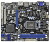
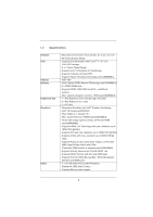
1.2 Specifications Platform CPU Chipset Memory Expansion Slot Graphics * Audio - Micro ATX Form Factor: 9.6-in x 8.6-in, 24.4 cm x 21.8 cm - All Solid Capacitor design - Supports 2nd Generation Intel® CoreTM i7 / i5 / i3 in LGA1155 Package - 4 + 1 Power Phase Design - Supports Intel® Turbo Boost - ASRock H67M | User Manual - Page 7
Rear Panel I/O SATA3 USB3.0 Connector BIOS Feature - PCIE x1 Gigabit LAN 10/100/1000 Mb/s - Realtek RTL8111E - Supports Wake-On-LAN - Supports LAN Cable Detection - Supports Energy Ef cient Ethernet 802.3az I/O Panel - 1 x PS/2 Keyboard Port - 1 x VGA/D-Sub Port - 1 x VGA/DVI-D Port - 1 x HDMI Port - ASRock H67M | User Manual - Page 8
- ACPI 1.1 Compliance Wake Up Events - Supports jumperfree - SMBIOS 2.3.1 Support - IGPU, DRAM, PCH, CPU PLL, VTT, VCCSA Voltage Multi-adjustment Support CD - Drivers, Utilities, AntiVirus Software (Trial Version), ASRock Software Suite (CyberLink DVD Suite - OEM and Trial; Creative Sound - ASRock H67M | User Manual - Page 9
procedures of ASRock Extreme Tuning Utility (AXTU). ASRock website: http://www.asrock.com 9. ASRock Instant Flash is a BIOS ash utility embedded in Flash ROM. This convenient BIOS update tool allows you to update system BIOS without entering operating systems rst like MS-DOS or Windows®. With this - ASRock H67M | User Manual - Page 10
as a game joystick to control your PC games. All you have to do is just to install the ASRock AIWI utility either from ASRock of cial website or ASRock software support CD to your motherboard, and also download the free AIWI Lite from App store to your iPhone/iPod touch. Connecting your PC and apple - ASRock H67M | User Manual - Page 11
under 1.00W in off mode condition. To meet EuP standard, an EuP ready motherboard and an EuP ready power supply are required. According to Intel's suggestion, the EuP ready power supply must meet the standard of 5v standby power ef ciency is higher than 50% under 100 mA current consumption. For EuP - ASRock H67M | User Manual - Page 12
SPDIF PWR_FAN1 LAN PHY 7 H67M CMOS Battery 8 SATA3_1 Top: LINE IN Center: FRONT Bottom: MIC IN SATA3 6Gb/s CHA_FAN1 32 HDMI 1.4a 31 PCIE1 PCI Express 2.0 ErP/EuP Ready RoHS Super I/O PCIE2 Intel 30 PCIE3 H67 1 CLRCMOS1 64Mb BIOS SATA2_3 SATA2_5 SATA2_2 SATA2_4 9 10 11 12 - ASRock H67M | User Manual - Page 13
1.4 I/O Panel 1 2 14 13 1 USB 2.0 Ports (USB01) 2 VGA/D-Sub Port * 3 LAN RJ-45 Port 4 Central / Bass (Orange) 5 Rear Speaker (Black) 6 Optical SPDIF Out Port 7 Line In (Light Blue) 3 47 58 69 12 11 10 ** 8 9 10 11 12 13 14 Front Speaker (Lime) Microphone (Pink) USB 2.0 Ports (USB45) USB - ASRock H67M | User Manual - Page 14
To enable Multi-Streaming function, you need to connect a front panel audio cable to the front panel audio header. After restarting your computer, you will nd "Mixer" tool on your system. Please select "Mixer ToolBox" , click "Enable playback multi-streaming", and click "ok". Choose "2CH", "4CH - ASRock H67M | User Manual - Page 15
grounded antistatic pad or in the bag that comes with the component. Before you install or remove any component, ensure that the power is switched off or the power cord is detached from the power supply. Failure to do so may cause severe damage to the motherboard, peripherals, and/or components. 15 - ASRock H67M | User Manual - Page 16
there is any bent pin on the socket. Do not force to insert the CPU into the socket if above situation is found. Otherwise, the CPU will be seriously damaged. Step 1. Open the socket: Step 1-1. Disengaging the the PnP cap. 2. This cap must be placed if returning the motherboard for after service. 16 - ASRock H67M | User Manual - Page 17
, please ensure to match the two orientation key notches of the CPU with the two alignment keys of the socket. Step 3-3. Carefully place the CPU into the socket by using a purely vertical motion. Step 3-4. Verify that the CPU is within the socket and properly mated to the orient keys. Step - ASRock H67M | User Manual - Page 18
CPU fan to the CPU_FAN connector (CPU_FAN1, see page 12, No. 1). For proper installation, please kindly refer to the instruction manuals of your CPU noticed that this motherboard supports Combo Cooler Option (C.C.O.), which provides the exible option to adopt three different CPU cooler types, Socket - ASRock H67M | User Manual - Page 19
Modules (DIMM) This motherboard provides two 240-pin DDR3 (Double Data Rate 3) DIMM slots, and supports Dual Channel Memory Technology. work on this motherboard. It is not recommended to install them on this motherboard. Installing a DIMM Please make sure to disconnect power supply before adding - ASRock H67M | User Manual - Page 20
lane width cards, such as Gigabit LAN card, SATA2 card, etc. PCIE1 switched off or the power cord is unplugged. Please read the documentation of the expansion card and make necessary hardware settings for the card before you start the installation. Remove the system unit cover (if your motherboard - ASRock H67M | User Manual - Page 21
VGA card to this motherboard. This motherboard also provides independent display controllers for DVI-D, D-Sub and HDMI to support dual VGA output so function after your system boots. If you haven't installed onboard VGA driver yet, please install onboard VGA driver from our support CD to your system - ASRock H67M | User Manual - Page 22
. 3. Boot your system. Press or to enter BIOS setup. motherboard. 4. Install the onboard VGA driver and the add-on PCI Express VGA card driver to your system. If you have installed the drivers already, there is no need to install them again. 5. Set up a multi-monitor display. For Windows - ASRock H67M | User Manual - Page 23
For Windows® 7 / 7 64-bit supported on this motherboard. To use HDCP function with this motherboard, you need to adopt the monitor that supports HDCP function as well. Therefore, you can enjoy the superior display quality with high-de nition HDCP encryption contents. Please refer to below instruction - ASRock H67M | User Manual - Page 24
you need to clear the CMOS when you just nish updating the BIOS, you must boot up the system rst, and then shut it down before you do the clear-CMOS action. Please be noted that the password, date, time, user default pro le, 1394 GUID and MAC address will be cleared only if the - ASRock H67M | User Manual - Page 25
caps over the headers and connectors will cause permanent damage of the motherboard! FDD connector (33-pin FLOPPY1) (see p.12 No. 25) ) SATA2_3 SATA2_2 SATA2_5 SATA2_4 These four Serial ATAII (SATAII) connectors support SATA data cables for internal storage devices. The current SATAII interface - ASRock H67M | User Manual - Page 26
P+9 GND DUMMY 1 GND P+8 P-8 USB_PWR USB_PWR P-11 P+11 GND DUMMY 1 GND P+10 P-10 USB_PWR Infrared Module Header (5-pin IR1) (see p.12 No. 6) IRTX +5VSB DUMMY 1 2.0 headers on this motherboard. Each USB 2.0 header can support two USB 2.0 ports. This header supports an optional wireless transmitting - ASRock H67M | User Manual - Page 27
For Windows® 7 / 7 64-bit / VistaTM / VistaTM 64-bit OS: Go to the "FrontMic" Tab in the Realtek Control panel. Adjust "Recording Volume". System Panel Header (9-pin PANEL1) (see p.12 No. 18) This header accommodates several system front panel functions. Connect the power switch, reset switch and - ASRock H67M | User Manual - Page 28
mainly consists of power switch, reset switch, power LED, hard drive motherboard provides 4-Pin CPU fan (Quiet Fan) support, the 3-Pin CPU fan still can work successfully even without the fan speed control function. If you plan to connect the 3-Pin CPU fan to the CPU fan connector on this motherboard - ASRock H67M | User Manual - Page 29
Power Supply Installation 1 13 ATX 12V Power Connector (8-pin ATX12V1) (see p.12 No. 2) 8 5 4 1 Please connect an ATX 12V power supply to this connector. Though this motherboard provides 8-pin ATX 12V power 4-Pin ATX 12V Power Supply Installation 4 1 This COM1 header supports a serial port - ASRock H67M | User Manual - Page 30
motherboard adopts Intel® H67 chipset that supports Serial ATA (SATA) / Serial ATAII (SATAII) hard disks and RAID (RAID 0, RAID 1, RAID 10, RAID 5 and Intel Rapid Storage) functions. You may install SATA / SATAII hard disks on this motherboard for internal storage devices. This section will guide - ASRock H67M | User Manual - Page 31
HDDs while the system is still power-on and in working condition. 2.13 Hot Plug and Hot Swap Functions for SATA3 HDDs This motherboard supports Hot Plug and Hot Swap functions for SATA3 in RAID / AHCI mode. Intel® H67 chipset provides hardware support for Advanced Host controller Interface (AHCI - ASRock H67M | User Manual - Page 32
installed into system properly. The latest SATA / SATAII / SATA3 driver is available on our support website: www.asrock.com 4. Make sure to use the SATA power cable & data cable, which are from our motherboard package. 5. Please follow below instructions step by step to reduce the risk of HDD crash - ASRock H67M | User Manual - Page 33
do follow below instruction sequence to process the Hot Plug, improper procedure will cause the SATA / SATAII / SATA3 HDD damage and data loss. Step 1 Please connect SATA power cable 1x4-pin end Step 2 Connect SATA data cable to (White) to the power supply 1x4-pin cable. the motherboard's SATAII - ASRock H67M | User Manual - Page 34
"SATA Mode" to [RAID]. STEP 2: Make a SATA / SATAII / SATA3 Driver Diskette. A. Insert the Support CD into your optical drive to boot your system. B. During POST at the beginning of system boot-up, press key, and then a window for boot devices selection appears. Please select CD-ROM as the - ASRock H67M | User Manual - Page 35
the document in the Support CD, "Guide to SATA Hard Disks Installation and RAID Con guration", which is located in the folder at the following path: .. \ RAID Installation Guide STEP 4: Install Windows® XP / XP 64-bit OS on your system. After making a SATA / SATAII / SATA3 driver diskette and using - ASRock H67M | User Manual - Page 36
5. Finish the Windows® installation and install all necessary drivers. 6. Install the Intel(R) Rapid Storage software via the CD-ROM included with your motherboard or after downloading it from the Internet. This will add the Intel(R) Rapid Storage Console which can be used to manage the RAID con - ASRock H67M | User Manual - Page 37
RAID Installation Guide and the document in the support CD, "Guide to Intel Rapid Storage", which is located in the folder at the following path: .. \ Intel Rapid Storage Information If you want to use "Intel Rapid Storage" in Windows® environment, please install "SATAII driver" from the Support CD - ASRock H67M | User Manual - Page 38
® XP / XP 64-bit Without RAID Functions If you want to install Windows® XP / XP 64-bit OS on your SATA / SATAII / SATA3 HDDs without RAID functions, please follow below steps. Using SATA / SATAII / SATA3 HDDs with NCQ function STEP 1: Set Up BIOS. A. Enter BIOS SETUP UTILITY Advanced screen SATA Con - ASRock H67M | User Manual - Page 39
64-bit Without RAID Functions If you want to install Windows® 7 / 7 64-bit / VistaTM / VistaTM 64-bit OS on your SATA / SATAII / SATA3 HDDs without RAID functions, please follow below steps. Using SATA / SATAII / SATA3 HDDs with NCQ function STEP 1: Set Up BIOS. A. Enter BIOS SETUP UTILITY Advanced - ASRock H67M | User Manual - Page 40
UEFI chip on the motherboard stores the UEFI SETUP UTILITY. You may run the UEFI SETUP UTILITY when you start up the computer. Please press or during the Power-On-Self-Test (POST) to enter the UEFI Because the UEFI software is constantly being updated, the following UEFI setup screens - ASRock H67M | User Manual - Page 41
up the selected screen To display the General Help Screen To load optimal default values for all the settings To save changes and exit the UEFI SETUP UTILITY To jump to the Exit Screen or exit the current screen 3.2 Main Screen When you enter the - ASRock H67M | User Manual - Page 42
con gurations for the following items: CPU Con guration, Intel IGD SWSCI OpRegion ASRock Instant Flash ASRock Instant Flash is a UEFI flash utility embedded in Flash ROM. This convenient UEFI update tool allows you to update system UEFI without entering operating systems rst like MS-DOS or Windows - ASRock H67M | User Manual - Page 43
[Auto], you need to set the "Power Schemes" as "Portable/Laptop" to enable this function. If you install Windows® VistaTM / 7 and want to enable this function, please set this item to [Enabled]. This item will be hidden if the current CPU does not support Intel SpeedStep technology. Please note that - ASRock H67M | User Manual - Page 44
(C1). The C1 state is supported through the native processor instructions HLT and MWAIT and requires no hardware support from the chipset. In the C1 power state, the processor maintains the context of the system caches. CPU C3 State Support Use this to enable or disable CPU C3 (ACPI C2) report to - ASRock H67M | User Manual - Page 45
the motherboard through ef cient memory utilization. In DVMT mode, the graphics driver allocates memory as needed for running graphics applications and is cooperatively using this memory with other system components. This item will not be used under Windows® VistaTM / 7 OS because the driver will - ASRock H67M | User Manual - Page 46
3.3.3 Integrated Clock Chip Configuration DIV-1S Integrated Clock Control options. DIV-2S Integrated Clock Control options. DIV3 Integrated Clock Control options. DIV4 Integrated Clock Control options. DIV-1NS Integrated Clock Control options. DIV-2NS Integrated Clock Control options. 46 - ASRock H67M | User Manual - Page 47
3.3.4 DRAM Configuration DRAM Frequency If [Auto] is selected, the motherboard will detect the memory module(s) inserted and assigns appropriate frequency automatically. CAS# Latency (tCL) Use this item to change CAS# Latency (tCL) Auto/Manual setting. The default is [Auto]. RAS# to CAS# Delay (tRCD - ASRock H67M | User Manual - Page 48
[Auto]. Read to Precharge (tRTP) Use this item to change Read to Precharge (tRTP) Auto/Manual setting. The default is [Auto]. Four Activate Window (tFAW) Use this item to change Four Activate Window (tFAW) Auto/Manual setting. The default is [Auto]. Memory Power Down Mode Use this item to adjust DDR - ASRock H67M | User Manual - Page 49
® Virtualization Technology for Directed I/O). The default value of this feature is [Disabled]. Primary Graphics Adapter This allows you to select the boot graphic adapter priority. Con guration options: [Onboard], [PCI Express] and [PCI]. The default value is [PCI]. Onboard VGA Share Memory This - ASRock H67M | User Manual - Page 50
boot up when the power recovers. Deep Sx Mobile platforms support Deep S4/S5 in DC only and desktop platforms support Deep S4/S5 in AC only. Con guration options: [Disabled], [Enabled in S5] and [Enabled in S4 and S5]. The default value is [Disabled]. Onboard LAN motherboard to submit Windows® VistaTM - ASRock H67M | User Manual - Page 51
Mode], [AHCI Mode] and [RAID Mode]. The default value is [IDE Mode]. AHCI (Advanced Host Controller Interface) supports NCQ and other new features that 1 Please select [Compatible] when you install legacy OS. If native OS (Windows® XP / VistaTM / 7) is installed, please select [Enhanced]. Hard Disk - ASRock H67M | User Manual - Page 52
3.3.8 Super IO Configuration OnBoard Floppy Controller Use this item to enable or disable oppy drive controller. Serial Port Use this item to enable or disable the onboard serial port. Serial Port Address Use this item to set the address for the onboard serial port. Con guration options: [Auto], [ - ASRock H67M | User Manual - Page 53
[Auto]. PCH Voltage Use this to select PCH Voltage. Con guration options: [Auto], [0.780V] to [1.646V]. The default value is [Auto]. CPU PLL Voltage Use this to select CPU PLL Voltage. Con guration options: [Auto], [1.548V] to [2.310V]. The default value is [Auto]. VTT Voltage Use this to select VTT - ASRock H67M | User Manual - Page 54
3.3.10 ACPI Configuration Suspend to RAM Use this item to select whether to auto-detect or disable the Suspend-toRAM feature. Select [Auto] will enable this feature if the OS supports it. PS/2 Keyboard Power On Use this item to enable or disable PS/2 keyboard to turn on the system from the power- - ASRock H67M | User Manual - Page 55
use under legacy OS and UEFI setup when [Disabled] is selected. If you have USB compatibility issue, it is recommended to select [Disabled] to enter OS. [UEFI Setup Only] - USB devices are allowed to use only under UEFI setup and Windows / Linux OS. Legacy USB 3.0 Support Use this option to enable - ASRock H67M | User Manual - Page 56
CPU temperature, motherboard temperature, CPU fan speed, chassis fan speed, and the critical voltage. CPU Fan Setting This allows you to set the CPU [Automatic Mode]. The default is value [Full On]. Power Fan Setting This allows you to set the power fan speed. Con guration options: [Full On] and - ASRock H67M | User Manual - Page 57
guration options: [Enabled] and [Disabled]. The default value is [Enabled]. Boot From Onboard LAN Use this item to enable or disable the Boot From Onboard LAN feature. Boot Failure Guard Enable or disable the feature of Boot Failure Guard. Boot Failure Guard Count Enable or disable the feature of - ASRock H67M | User Manual - Page 58
3.6 Security Screen In this section, you may set or change the supervisor/user password for the system. For the user password, you may also clear it. 58 - ASRock H67M | User Manual - Page 59
. Discard Changes When you select this option, it will pop-out the following message, "Discard changes?" Select [OK] to discard all changes. Load UEFI Defaults Load UEFI default values for all the setup questions. F9 key can be used for this operation. User Default In this option, you are allowed to - ASRock H67M | User Manual - Page 60
information. 4.2 Support CD Information The Support CD that came with the motherboard contains necessary drivers and useful utilities that enhance the motherboard features. 4.2.1 Running The Support CD To begin using the support CD, insert the CD into your CD-ROM drive. The CD automatically displays - ASRock H67M | User Manual - Page 61
HDD Larger Than 2TB This motherboard is adopting UEFI BIOS that allows Windows® OS to be installed on a large size HDD (>2TB). Please follow below procedure to install the operating system. 1. Please make sure to use Windows® VistaTM 64-bit (with SP1 or above) or Windows® 7 64-bit. 2. Press or
-
 1
1 -
 2
2 -
 3
3 -
 4
4 -
 5
5 -
 6
6 -
 7
7 -
8
-
9
-
10
-
11
-
12
-
13
-
14
-
15
-
16
-
17
-
18
-
19
-
20
-
21
-
22
-
23
-
24
-
25
-
26
-
27
-
28
-
29
-
30
-
31
-
32
-
33
-
34
-
35
-
36
-
37
-
38
-
39
-
40
-
41
-
42
-
43
-
44
-
45
-
46
-
47
-
48
-
49
-
50
-
51
-
52
-
53
-
54
-
55
-
56
-
57
-
58
-
59
-
60
-
61
 |
 |

1
H67M
User Manual
Version 1.0
Published October 2010
Copyright©2010 ASRock INC. All rights reserved.