ASRock H67M User Manual - Page 26
Consumer Infrared Module Header
 |
View all ASRock H67M manuals
Add to My Manuals
Save this manual to your list of manuals |
Page 26 highlights
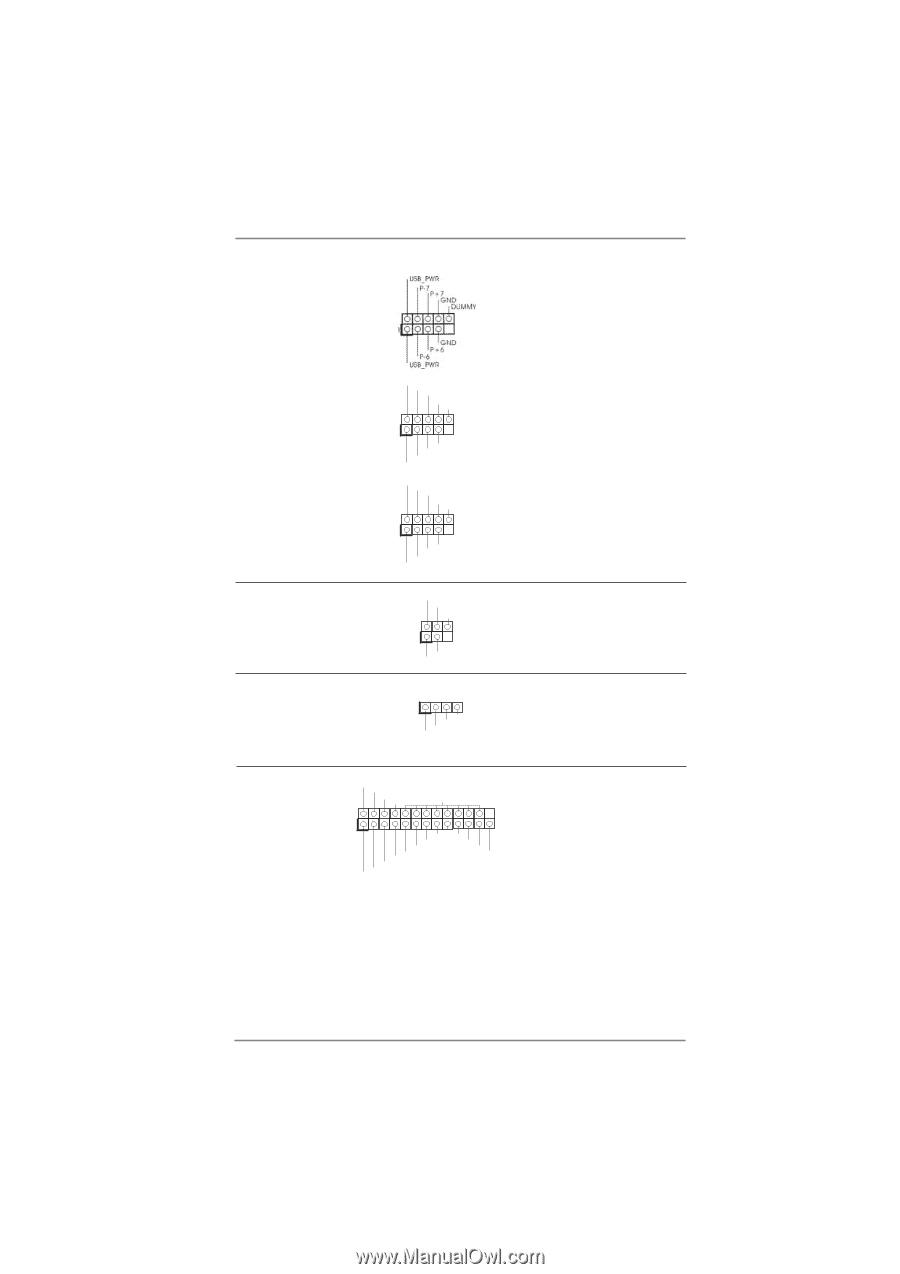
USB 2.0 Headers (9-pin USB6_7) (see p.12 No. 22) (9-pin USB8_9) (see p.12 No. 19) (9-pin USB10_11) (see p.12 No. 20) USB_PWR P-9 P+9 GND DUMMY 1 GND P+8 P-8 USB_PWR USB_PWR P-11 P+11 GND DUMMY 1 GND P+10 P-10 USB_PWR Infrared Module Header (5-pin IR1) (see p.12 No. 6) IRTX +5VSB DUMMY 1 GND IRRX Consumer Infrared Module Header (4-pin CIR1) (see p.12 No. 23) 1 GND IRTX IRRX ATX+5VSB Besides four default USB 2.0 ports on the I/O panel, there are three USB 2.0 headers on this motherboard. Each USB 2.0 header can support two USB 2.0 ports. This header supports an optional wireless transmitting and receiving infrared module. This header can be used to connect the remote controller receiver. Print Port Header (25-pin LPT1) (see p.12 No. 24) AFD# ERROR# PINIT# SLIN# GND 1 SPD7 SPD6 ACK# SPD5 BUSY SPD4 PE SPD3 SLCT SPD2 SPD1 SPD0 STB# This is an interface for print port cable that allows convenient connection of printer devices. 26
-
 1
1 -
2
-
3
-
4
-
5
-
6
-
7
-
8
-
9
-
10
-
11
-
12
-
13
-
14
-
15
-
16
-
17
-
18
-
19
-
20
-
 21
21 -
 22
22 -
 23
23 -
 24
24 -
 25
25 -
 26
26 -
 27
27 -
 28
28 -
 29
29 -
 30
30 -
 31
31 -
32
-
33
-
34
-
35
-
36
-
37
-
38
-
39
-
40
-
41
-
42
-
43
-
44
-
45
-
46
-
47
-
48
-
49
-
50
-
51
-
52
-
53
-
54
-
55
-
56
-
57
-
58
-
59
-
60
-
61
 |
 |