ASRock K10N750SLI-WiFi User Manual
ASRock K10N750SLI-WiFi Manual
 |
View all ASRock K10N750SLI-WiFi manuals
Add to My Manuals
Save this manual to your list of manuals |
ASRock K10N750SLI-WiFi manual content summary:
- ASRock K10N750SLI-WiFi | User Manual - Page 1
K10N750SLI-WiFi User Manual Version 1.0 Published March 2008 Copyright©2008 ASRock INC. All rights reserved. 1 - ASRock K10N750SLI-WiFi | User Manual - Page 2
any form or by any means, except duplication of documentation by the purchaser for backup purpose, without written consent of ASRock Inc. Products and corporate names appearing in this manual may or may not be registered trademarks or copyrights of their respective companies, and are used only for - ASRock K10N750SLI-WiFi | User Manual - Page 3
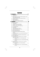
Supported PCI Express VGA Card List for SLITM Mode 11 1.5 Motherboard Layout 12 1.6 ASRock WiFi_SPDIF I/O 13 1.7 ASRock WiFi-802.11g Module 39 2.13 SATA / SATAII HDD Hot Plug Feature and Operation Guide ....... 40 2.14 Driver Installation Guide 42 2.15 Installing Windows® XP / XP 64-bit / VistaTM - ASRock K10N750SLI-WiFi | User Manual - Page 4
2.17 DTS Operation Guide 46 2.18 Untied Overclocking Technology 48 3 . BIOS SETUP UTILITY 4 9 3.1 Introduction 49 3.1.1 BIOS Menu Bar 49 67 4 . Software Support 68 4.1 Install Operating System 68 4.2 Support CD Information 68 4.2.1 Running Support CD 68 4.2.2 Drivers Menu 68 4.2.3 Utilities - ASRock K10N750SLI-WiFi | User Manual - Page 5
(ATX Form Factor: 12.0-in x 8.8-in, 30.5 cm x 22.4 cm) ASRock K10N750SLI-WiFi Quick Installation Guide ASRock K10N750SLI-WiFi Support CD ASRock WiFi-802.11g Module Operation Guide Motherboard Accessories One ASRock SLI Bridge One ASRock SLI/XFire Switch Card One 80-conductor Ultra ATA 66/100/133 IDE - ASRock K10N750SLI-WiFi | User Manual - Page 6
range (ALC890 Audio Codec) - DTS (Digital Theater Systems) support (see CAUTION 8) - Gigabit LAN 10/100/1000 Mb/s - Giga PHY Realtek RTL8211B - Supports Wake-On-LAN - ASRock WiFi-802.11g module - 54Mbps IEEE 802.11g / 11Mbps IEEE 802.11b - Supports Software Access Point mode (AP mode) and Station - ASRock K10N750SLI-WiFi | User Manual - Page 7
12) - 1 x WiFi/E header (see CAUTION 13) - 8Mb AMI BIOS - AMI Legal BIOS - Supports "Plug and Play" - ACPI 1.1 Compliance Wake Up Events - Supports jumperfree - AMBIOS 2.3.1 Support - CPU, DRAM, NB, SB, VTT Voltage Multi-adjustment - Drivers, Utilities, AntiVirus Software (Trial Version) - ASRock OC - ASRock K10N750SLI-WiFi | User Manual - Page 8
If you want to use SLITM function, please follow the instructions on page 21 to reverse the direction of ASRock SLI/XFire Switch Card. For the information of the compatible SLITM Mode PCI Express VGA cards, please refer to the "Supported PCI Express VGA Card List for SLITM Mode" on page 11. For the - ASRock K10N750SLI-WiFi | User Manual - Page 9
eSATAII installation procedures. 12. Power Management for USB 2.0 works fine under Microsoft® Windows® VistaTM 64-bit / VistaTM / XP 64-bit / XP SP1 or SP2. 13. WiFi/E header supports WiFi+AP function with ASRock WiFi-802.11g or WiFi-802.11n module, an easy-to-use wireless local area network (WLAN - ASRock K10N750SLI-WiFi | User Manual - Page 10
system. 18. This motherboard supports ASRock AM2 Boost overclocking technology for AM2 CPU. If you enable this function in the BIOS setup, the memory performance system memory (Premium) 512MB system memory (Basic) DX10 with WDDM Driver with 128bit VGA memory (Premium) with 64bit VGA memory (Basic) - ASRock K10N750SLI-WiFi | User Manual - Page 11
6600 GeForce 7900GS GeForce 7300GS GeForce 7300GT * These two cards can only work under Windows® XP / XP 64-bit OS. For the latest updates of the supported PCI Express VGA card list for SLITM Mode, please visit our website for details. ASRock website: http://www.asrock.com/support/index.htm 11 - ASRock K10N750SLI-WiFi | User Manual - Page 12
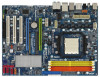
K10N750SLI-WiFi CPU_FAN1 PCI EXPRESS RAID Dual Channel LAN PHY PCIE2 PCI Express 2.0 CMOS BATTERY Super I/O AUDIO CODEC CD1 1 HD_AUDIO1 IR1 HDMI_SPDIF1 1 1 FLOPPY1 PCIE3 PCI1 NVIDIA nForce 750a SLI Chipset PCI2 PCI3 RoHS FRONT_1394 1 1394a 8Mb BIOS SATAII_2 (PORT1) CHA_FAN1 - ASRock K10N750SLI-WiFi | User Manual - Page 13
1.6 ASRock WiFi_SPDIF I/O 1 2 3 4 7 5 8 6 9 16 15 14 13 12 11 10 1 PS/2 Mouse Port (Green) 2 IEEE 1394 Port * 3 LAN RJ-45 Port 4 Side Speaker (Gray) 5 Rear Speaker (Black) 6 - ASRock K10N750SLI-WiFi | User Manual - Page 14
64-bit Compatibility - Full compatible with IEEE 802.11g standard products Software Support - ASRock WiFi-802.11g Wizard If you want to start to use ASRock WiFi-802.11g module on this motherboard, please carefully read "ASRock WiFi-802.11g Module Operation Guide" in the package for the detailed - ASRock K10N750SLI-WiFi | User Manual - Page 15
2. Installation This is an ATX form factor (12.0-in x 8.8-in, 30.5 cm x 22.4 cm) motherboard. Before you install the motherboard, study the configuration of your chassis to ensure that the motherboard fits into it. Pre-installation Precautions Take note of the following precautions before you - ASRock K10N750SLI-WiFi | User Manual - Page 16
each other. Then connect the CPU fan to the CPU FAN connector (CPU_FAN1, see Page 12, No. 4). For proper installation, please kindly refer to the instruction manuals of the CPU fan and the heatsink. 16 - ASRock K10N750SLI-WiFi | User Manual - Page 17
2.3 Installation of Memory Modules (DIMM) This motherboard provides four 240-pin DDR2 (Double Data Rate 2) DIMM slots, and supports Dual Channel Memory Technology. For dual channel configuration, you always need to install identical (the same brand, speed, size and chip-type) DDR2 DIMM pair - ASRock K10N750SLI-WiFi | User Manual - Page 18
Installing a DIMM Please make sure to disconnect power supply before adding or removing DIMMs or the system components. Step 1. Step 2. Unlock a DIMM slot by pressing the retaining clips outward. Align a DIMM on the slot such that the notch on the DIMM matches the break on the slot. notch break - ASRock K10N750SLI-WiFi | User Manual - Page 19
; White) is used for PCI Express cards with x1 lane width cards, such as Gigabit LAN card, SATA2 card and ASRock PCIE_DE card. PCIE2 (PCIE x16 slot; Green) is used for PCI Express x16 lane width graphics cards, or used to install PCI Express graphics cards to support SLITM function. PCIE3 (PCIE x16 - ASRock K10N750SLI-WiFi | User Manual - Page 20
or lose ASRock SLI/XFire Switch Card when it is still in working condition. 2. For the information of the compatible SLITM Mode PCI Express VGA cards and SLITM setup procedures, please refer to the "Supported PCI Express VGA Card List for SLITM Mode" on page 11 and "SLITM Operation Guide" on page - ASRock K10N750SLI-WiFi | User Manual - Page 21
graphics card driver supports the NVIDIA® SLITM technology. Download the latest driver from the NVIDIA® website (www.nvidia.com). 3. Make sure that your power supply unit (PSU) can provide at least the minimum power required by your system. Enjoy the benefit of SLITM Step 1. There is one ASRock SLI - ASRock K10N750SLI-WiFi | User Manual - Page 22
. Also, keep away from touching the connectors (Golden Fingers). Step 5. Install the identical SLITM-ready graphics cards that are NVIDIA® certified because different types of graphics cards will not work together properly. (Even the GPU chips version shall be the same.) Insert one graphics - ASRock K10N750SLI-WiFi | User Manual - Page 23
inserted to PCIE2 slot. Connect a 4-pin ATX power cable to SLI/XFIRE power connector. Step 10. Install the graphics card drivers to your system. After that, you can enable the Multi-Graphics Processing Unit (GPU) feature in the NVIDIA® nView system tray utility. Please follow the - ASRock K10N750SLI-WiFi | User Manual - Page 24
E. From the Display Properties dialog box, select the Settings tab then click Advanced. F. Select the NVIDIA GeForce tab. G. Click the slider to display the following screen, then select the SLI multi-GPU item. H. Click the Enable SLI multi-GPU check box. I. Click OK when done. 24 - ASRock K10N750SLI-WiFi | User Manual - Page 25
For Windows® VistaTM / VistaTM 64-bit OS: A. Click the Start icon on your Windows taskbar. B. From the pop-up menu, select All Programs, and then click NVIDIA Corporation. C. Select NVIDIA Control Panel tab. D. Select Control Panel tab. E. From the pop-up menu, select Set SLI configuration, and then - ASRock K10N750SLI-WiFi | User Manual - Page 26
and pin3 on CLRCMOS1 for 5 seconds. However, please do not clear the CMOS right after you update the BIOS. If you need to clear the CMOS when you just finish updating the BIOS, you must boot up the system first, and then shut it down before you do the clear-CMOS action - ASRock K10N750SLI-WiFi | User Manual - Page 27
devices 80-conductor ATA 66/100/133 cable Note: Please refer to the instruction of your IDE device vendor for the details. Serial ATA II Connectors (SATAII_1 ) SATAII_5 (PORT4) These six Serial ATAII (SATAII) connectors support SATA data cables for internal storage devices. The current SATAII - ASRock K10N750SLI-WiFi | User Manual - Page 28
on the I/O panel, there are two USB 2.0 headers on this motherboard. Each USB 2.0 header can support two USB 2.0 ports. This header supports WiFi+AP function with ASRock WiFi-802.11g or WiFi-802.11n module, an easy-to-use wireless local area network (WLAN) adapter. It allows you to create a wireless - ASRock K10N750SLI-WiFi | User Manual - Page 29
allows convenient connection and control of audio devices. 1. High Definition Audio supports Jack Sensing, but the panel wire on the chassis must support HDA to function correctly. Please follow the instruction in our manual and chassis manual to install your system. 2. If you use AC'97 audio panel - ASRock K10N750SLI-WiFi | User Manual - Page 30
cable to this connector and match the black wire to the ground pin. Though this motherboard provides 4-Pin CPU fan (Quiet Fan) support, the 3-Pin CPU fan still can work successfully even without the fan speed control function. If you plan to connect the 3-Pin CPU fan to the CPU fan connector - ASRock K10N750SLI-WiFi | User Manual - Page 31
still work if pin ATX 12V power connector, it can still work if you adopt a traditional 4-pin ATX a hard disk power connecor when two graphics cards are plugged to this motherboard at the same time ) on this motherboard. This IEEE 1394 header can support one IEEE 1394 port. Serial port Header (9-pin - ASRock K10N750SLI-WiFi | User Manual - Page 32
TV/ projector/LCD devices. Please connect the HDMI_SPDIF connector of HDMI VGA card to this header. HDMI_SPDIF Cable (Optional) C B A Please connect end (B or C) of HDMI_SPDIF cable to the HDMI_SPDIF connector of HDMI VGA card. A. black end +5V SPDIFOUT GND B. white end (2-pin) C. white end - ASRock K10N750SLI-WiFi | User Manual - Page 33
refer to the VGA card user manual for connector usage in advance. Connect the HDMI output connector on HDMI VGA card to HDMI device, such as HDTV. Please refer to the user manual of HDTV and HDMI VGA card vendor for detailed connection procedures. Install HDMI VGA card driver to your system. 33 - ASRock K10N750SLI-WiFi | User Manual - Page 34
remove your eSATAII devices to the eSATAII ports while the system is power-on and in working condition. 2. If you set "SATA Operation Mode" option in BIOS setup to non-RAID mode, Hot Plug function is not supported with eSATAII devices. If you still want to use eSATAII function in non-RAID mode - ASRock K10N750SLI-WiFi | User Manual - Page 35
How to install eSATAII? SATAII_6 (PORT5) eSATAII_TOP 1. In order to enable the eSATAII port of the I/O shield, you need to connect the orange SATAII connector (SATAII_6 (PORT5); see p.12 No.12) and the eSATAII connector (eSATAII_TOP; see p.12 No.38) with a SATA data cable first. Connect the SATA - ASRock K10N750SLI-WiFi | User Manual - Page 36
Comparison between eSATAII and other devices IEEE 1394 USB 2.0 SATA eSATAII/SATAII 400Mb/s 480Mb/s 1.5Gb/s (1500Mb/s) 3.0Gb/s (3000Mb/s) 36 - ASRock K10N750SLI-WiFi | User Manual - Page 37
guide. Some default setting of SATAII hard disks may not be at SATAII mode, which operate with the best performance. In order to enable SATAII function, please follow the below instruction 's website for details: http://www.hitachigst.com/hdd/support/download.htm The above examples are just for your - ASRock K10N750SLI-WiFi | User Manual - Page 38
Hard Disks Installation This motherboard adopts NVIDIA® nForce 750a SLI chipset that supports Serial ATA (SATA) / Serial ATAII (SATAII) hard disks and hard disks on this motherboard for internal storage devices. This section will guide you to install the SATA / SATAII hard disks. STEP 1: Install - ASRock K10N750SLI-WiFi | User Manual - Page 39
AHCI mode. NVIDIA® nForce 750a SLI chipset provides hardware support for Advanced Host controller Interface (AHCI), a new programming interface SATA / SATAII HDDs while the system is still power-on and in working condition. eSATAII is equipped with Hot Plug capability that enables you to exchange - ASRock K10N750SLI-WiFi | User Manual - Page 40
is installed into system properly. The latest SATA / SATAII driver is available on our support website: www.asrock.com 4. Make sure to use the SATA power cable & data cable, which are from our motherboard package. 5. Please follow below instructions step by step to reduce the risk of HDD crash or - ASRock K10N750SLI-WiFi | User Manual - Page 41
the SATA / SATAII HDD. How to Hot Unplug a SATA / SATAII HDD: Points of attention, before you process the Hot Unplug: Please do follow below instruction sequence to process the Hot Unplug, improper procedure will cause the SATA / SATAII HDD damage and data loss. Step 1 Unplug SATA data cable from - ASRock K10N750SLI-WiFi | User Manual - Page 42
NCQ and Hot Plug functions STEP 1: Set Up BIOS. A. Enter BIOS SETUP UTILITY Advanced screen IDE Configuration. B. Set the "SATA Operation Mode" option to [non-RAID]. STEP 2: Make a SATA / SATAII driver diskette. A. Insert the ASRock Support CD into your optical drive to boot your system - ASRock K10N750SLI-WiFi | User Manual - Page 43
STEP 1: Set Up BIOS. A. Enter BIOS SETUP UTILITY Advanced instruction to install Windows® VistaTM / Windows® VistaTM 64-bit OS on your system. When you see "Where do you want to install Windows? " page, please insert the ASRock Support CD into your optical drive, and click the "Load Driver - ASRock K10N750SLI-WiFi | User Manual - Page 44
configure RAID function, you need to check the RAID installation guide in the Support CD for proper configuration. Please refer to the BIOS RAID installation guide part of the document in the following path in the Support CD: .. \ RAID Installation Guide STEP 5: Install Windows® XP / XP 64-bit OS on - ASRock K10N750SLI-WiFi | User Manual - Page 45
to boot your system, and follow the instruction to install Windows® VistaTM / Windows® VistaTM 64-bit OS on your system. When you see "Where do you want to install Windows? " page, please insert the ASRock Support CD into your optical drive, and click the "Load Driver" button on the left on the - ASRock K10N750SLI-WiFi | User Manual - Page 46
2.17 DTS Operation Guide DTS (Digital Theater Systems) is a multi-channel digital surround dramatically improves content. Please follow below steps to enable DTS function: 1. Install the drivers to your system from ASRock support CD. 2. Reboot your system. 3. You will find the icon (Realtek HD - ASRock K10N750SLI-WiFi | User Manual - Page 47
Music Mode Cinema Mode Music Mode The music mode is for use with any stereo music recordings, which preserves the integrity of the stereo mix while augmenting it with a center channel to anchor the image, and deriving enough surround content to yield a spacious, three-dimensional listening - ASRock K10N750SLI-WiFi | User Manual - Page 48
8 Untied Overclocking Technology This motherboard supports Untied Overclocking Technology, which means during overclocking, FSB enjoys better margin due to fixed PCI / PCIE buses. Before you enable Untied Overclocking function, please enter "Overclock Mode" option of BIOS setup to set the selection - ASRock K10N750SLI-WiFi | User Manual - Page 49
up the system time/date information Advanced To set up the advanced BIOS features H/W Monitor To display current hardware status Boot To set up To set up the security features Exit To exit the current screen or the BIOS SETUP UTILITY Use < > key or < > key to choose among the selections - ASRock K10N750SLI-WiFi | User Manual - Page 50
SETUP UTILITY Main Advanced H/W Monitor Boot Security Exit System Overview System Time System Date [17:00:09] [Fri 02/01/2008] BIOS Version : K10N750SLI-WiFi P1.0 Processor Type : AMD Athlon(tm) 64 X2 Dual Core Processor 6000+ (64bit) Processor Speed : 3000MHz Microcode Update : 40F33/0 L1 Cache - ASRock K10N750SLI-WiFi | User Manual - Page 51
malfunction. 3.3.1 CPU Configuration BIOS SETUP UTILITY Advanced CPU voltage will be left at the rated frequency/voltage. If Manual, multiplier and voltage will be set based on User Selection this option to [Enabled], you will enable ASRock AM2 Boost function, which will improve the memory - ASRock K10N750SLI-WiFi | User Manual - Page 52
frequency, and lead to system stability or compatibility issue with some memory modules or power supplies. Please set this item to [Disable] if above This item is set to [Auto] by default. If it is set to [Manual], you may adjust the value of Processor Frequency and Processor Voltage. However, it - ASRock K10N750SLI-WiFi | User Manual - Page 53
BIOS SETUP UTILITY Advanced CPU Configuration AM2 Boost Overclock Mode CPU Frequency ( appears only when you adopt AM2 CPU. This item will show when "Multiplier/Voltage Change" is set to [Manual]; otherwise, it will be hidden. The range of the value depends on the CPU you adopt on this motherboard - ASRock K10N750SLI-WiFi | User Manual - Page 54
CPU Voltage This option appears only when you adopt Phenom CPU. It allows you to adjust the value of CPU voltage. However, for safety and system stability, it is not recommended to adjust the value of this item. NB Frequency Multiplier This option appears only when you adopt Phenom CPU. However, for - ASRock K10N750SLI-WiFi | User Manual - Page 55
TWR Use this to adjust TWR values. Configuration options: [Auto], [3CLK], [4CLK], [5CLK] and [6CLK]. The default value is [Auto]. TWTR Use this to adjust TWTR values. Configuration options: [Auto], [1CLK], [2CLK] and [3CLK]. The default value is [Auto]. TRWTTO This option appears only when you adopt - ASRock K10N750SLI-WiFi | User Manual - Page 56
BIOS If you select [Auto], the onboard HD Audio will be disabled when PCI Sound Card is plugged. Front Panel Select [Auto], [Enabled] or [Disabled] for the this motherboard to support Hybrid SLITM function. This item is available only when the total capacity of the memory module you adopt is above - ASRock K10N750SLI-WiFi | User Manual - Page 57
options: [Auto], [1.20V], [1.25V], [1.30V] and [1.35V]. The default value is [Auto]. 3.3.3 ACPI Configuration BIOS SETUP UTILITY Advanced ACPI Settings Suspend To RAM Repost Video on STR Resume Check Ready Bit Away Mode Support Restore on AC / Power Loss Ring-In Power On PCI Devices Power On PS - ASRock K10N750SLI-WiFi | User Manual - Page 58
Restore on AC/Power Loss This allows you to set the power state after an unexpected AC/power loss. If [Power Off] is selected, the AC/power remains off when the power recovers. If [Power On] is selected, the AC/power resumes and the system starts to boot up when the power recovers. Ring-In Power On - ASRock K10N750SLI-WiFi | User Manual - Page 59
RAID] mode, SATA / SATAII HDDs can not be accessed until you finish configuring RAID functions in NVIDIA BIOS / Windows RAID Utility. * If you install OS on SATA / SATAII HDDs, please do not change in the following instruction, which can be applied to the configurations of "IDE1 Slave" as well. 59 - ASRock K10N750SLI-WiFi | User Manual - Page 60
BIOS SETUP UTILITY Advanced IDE Master Device Vendor Size LBA Mode Block Mode PIO Mode Async DMA Ultra DMA S.M.A.R.T. :Hard Disk :MAXTOR 6L080J4 :80.0 GB :Supported :16Sectors :4 :MultiWord DMA-2 :Ultra DMA-6 :Supported selecting the hard disk information into BIOS, use a disk utility, such as - ASRock K10N750SLI-WiFi | User Manual - Page 61
to maximize the IDE hard disk data transfer rate. 3.3.5 PCIPnP Configuration BIOS SETUP UTILITY Advanced Advanced PCI / PnP Settings PCI Latency Timer PCI IDE keep the default value unless the installed PCI expansion cards' specifications require other settings. PCI IDE BusMaster Use this item - ASRock K10N750SLI-WiFi | User Manual - Page 62
Serial Port Address Infrared Port Address [Enabled] [3F8 / IRQ4] [Disabled] Allow BIOS to Enable or Disable Floppy Controller. +F1 F9 F10 ESC Select Screen Select / IRQ3], and [2E8 / IRQ3]. If you plan to use ASRock DeskExpress on this motherboard, please keep this item on [Disabled] option. 62 - ASRock K10N750SLI-WiFi | User Manual - Page 63
this item to enable or disable the USB 2.0 support. Legacy USB Support Use this option to select legacy support for USB devices. There are four configuration options: [Enabled], [Auto], [Disabled] and [BIOS Setup Only]. The default value is [BIOS Setup Only]. Please refer to below descriptions for - ASRock K10N750SLI-WiFi | User Manual - Page 64
, including the parameters of the CPU temperature, motherboard temperature, CPU fan speed, chassis fan speed, and the critical voltage. BIOS SETUP UTILITY Main Advanced H/W Monitor Boot Security Exit Hardware Health Event Monitoring CPU Temperature M / B Temperature CPU Fan Speed Chassis - ASRock K10N750SLI-WiFi | User Manual - Page 65
(C) Copyright 1985-2003, American Megatrends, Inc. 3.5.1 Boot Settings Configuration BIOS SETUP UTILITY Boot Boot Settings Configuration Full Screen Logo AddOn ROM Display Boot : [Auto], [Aircraft], [Scenery] and [ASRock]. The default value is [Auto]. Currently, the option [Auto] is set to Aircraft - ASRock K10N750SLI-WiFi | User Manual - Page 66
you may set or change the supervisor/user password for the system. For the user password, you may also clear it. BIOS SETUP UTILITY Main Advanced H/W Monitor Boot Security Exit Security Settings Supervisor Password : Not Installed User Password : Not Installed Change Supervisor Password - ASRock K10N750SLI-WiFi | User Manual - Page 67
and exit setup?" Select [OK] to save the changes and exit the BIOS SETUP UTILITY. Discard Changes and Exit When you select this option, it message, "Discard changes and exit setup?" Select [OK] to exit the BIOS SETUP UTILITY without saving any changes. Discard Changes When you select this option - ASRock K10N750SLI-WiFi | User Manual - Page 68
install the necessary drivers to activate the devices. 4.2.3 Utilities Menu The Utilities Menu shows the applications software that the motherboard supports. Click on a specific item then follow the installation wizard to install it. 4.2.4 Contact Information If you need to contact ASRock or want to
-
 1
1 -
 2
2 -
 3
3 -
 4
4 -
 5
5 -
 6
6 -
 7
7 -
8
-
9
-
10
-
11
-
12
-
13
-
14
-
15
-
16
-
17
-
18
-
19
-
20
-
21
-
22
-
23
-
24
-
25
-
26
-
27
-
28
-
29
-
30
-
31
-
32
-
33
-
34
-
35
-
36
-
37
-
38
-
39
-
40
-
41
-
42
-
43
-
44
-
45
-
46
-
47
-
48
-
49
-
50
-
51
-
52
-
53
-
54
-
55
-
56
-
57
-
58
-
59
-
60
-
61
-
62
-
63
-
64
-
65
-
66
-
67
-
68
 |
 |
1
K10N750SLI-WiFi
User Manual
Version 1.0
Published March 2008
Copyright©2008 ASRock INC. All rights reserved.