ASRock K10N750SLI-WiFi User Manual - Page 28
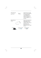
This header supports WiFi+AP - wifi module
 |
View all ASRock K10N750SLI-WiFi manuals
Add to My Manuals
Save this manual to your list of manuals |
Page 28 highlights
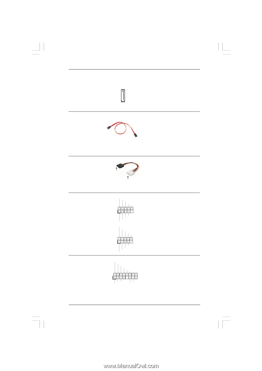
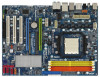
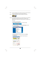
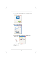
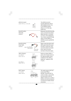
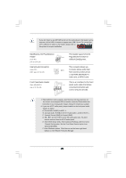
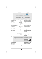
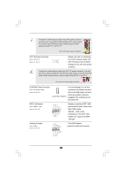
eSATAII_TOP eSATAII Connector (eSATAII_TOP: see p.12, No. 38) Serial ATA (SATA) Data Cable (Optional) Serial ATA (SATA) Power Cable (Optional) connect to the SATA HDD power connector connect to the power supply USB 2.0 Headers (9-pin USB8_9) (see p.12 No. 18) (9-pin USB6_7) (see p.12 No. 19) WiFi/E Header (15-pin WIFI/E) (see p.12 No. 35) USB_PWR P-9 P+9 GND DUMMY 1 GND P+8 P-8 USB_PWR USB_PWR P-7 P+7 GND DUMMY 1 GND P+6 P-6 USB_PWR USB+5V_2 TXN TXP GND2 PCIE_RST# + 3SVB RXN RXP 1 GND1 D0-D0+ PexCLK PexCLK# USB+5V_1 PME# 28 This eSATAII connector supports SATA data cable for external SATAII function. The current eSATAII interface allows up to 3.0 Gb/s data transfer rate. Either end of the SATA data cable can be connected to the SATA / SATAII hard disk or the SATAII connector on this motherboard. You can also use the SATA data cable to connect SATAII_6 (PORT5) connector and eSATAII connector. Please connect the black end of SATA power cable to the power connector on each drive. Then connect the white end of SATA power cable to the power connector of the power supply. Besides six default USB 2.0 ports on the I/O panel, there are two USB 2.0 headers on this motherboard. Each USB 2.0 header can support two USB 2.0 ports. This header supports WiFi+AP function with ASRock WiFi-802.11g or WiFi-802.11n module, an easy-to-use wireless local area network (WLAN) adapter. It allows you to create a wireless environment and enjoy the convenience of wireless network connectivity.
-
 1
1 -
2
-
3
-
4
-
5
-
6
-
7
-
8
-
9
-
10
-
11
-
12
-
13
-
14
-
15
-
16
-
17
-
18
-
19
-
20
-
21
-
22
-
 23
23 -
 24
24 -
 25
25 -
 26
26 -
 27
27 -
 28
28 -
 29
29 -
 30
30 -
 31
31 -
 32
32 -
 33
33 -
34
-
35
-
36
-
37
-
38
-
39
-
40
-
41
-
42
-
43
-
44
-
45
-
46
-
47
-
48
-
49
-
50
-
51
-
52
-
53
-
54
-
55
-
56
-
57
-
58
-
59
-
60
-
61
-
62
-
63
-
64
-
65
-
66
-
67
-
68
 |
 |