ASRock K7VT6-C Quick Installation Guide - Page 11
Connectors, English
 |
View all ASRock K7VT6-C manuals
Add to My Manuals
Save this manual to your list of manuals |
Page 11 highlights
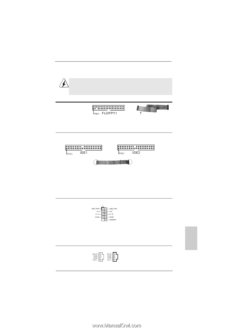
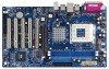
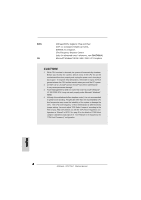
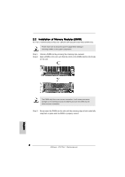
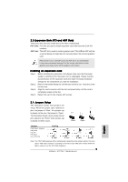
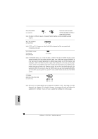
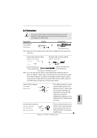
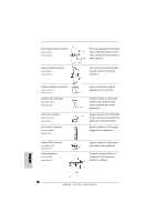
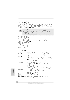
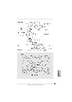
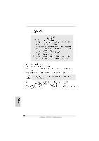
2.5 Connectors Connectors are NOT jumpers. DO NOT place jumper caps over these connectors. Placing jumper caps over the connectors will cause permanent damage of the motherboard! Connector FDD Connector (33-pin FLOPPY1) (see p.2 item 16) Figure Description the red-striped side to Pin1 Note: Make sure the red-striped side of the cable is plugged into Pin1 side of the connector. Primary IDE Connector (Blue) (39-pin IDE1, see p.2 item 8) Secondary IDE Connector (Black) (39-pin IDE2, see p.2 item 7) connect the blue end connect the black end to the motherboard to the IDE devices 80-conductor, ATA 66/100/133 cable Note: If you use only one IDE device on this motherboard, please set the IDE device as "Master". Please refer to the instruction of your IDE device vendor for the details. Besides, to optimize compatibility and performance, please connect your hard disk drive to the primary IDE connector (IDE1, blue) and CD-ROM to the secondary IDE connector (IDE2, black). Shared USB 2.0 Header (9-pin JUSB45) (see p.2 item 25) This USB45 connector is shared with the USB 2.0 ports 4,5 on ASRock I/O PlusTM. When using the front panel USB ports by attaching the front panel USB cable to this connector (JUSB45), the USB ports 4,5 on ASRock I/O PlusTM will not be able to function. Internal Audio Connectors These connectors allow you to (4-pin CD1, 4-pin AUX1) receive stereo audio input from (CD1: see p.2 item 17) sound sources such as a CD- (AUX1: see p.2 item 18) AUX1 CD1 ROM, DVD-ROM, TV tuner card, or MPEG card. 11 ASRock K7VT6-C Motherboard English
-
 1
1 -
2
-
3
-
4
-
5
-
 6
6 -
 7
7 -
 8
8 -
 9
9 -
 10
10 -
 11
11 -
 12
12 -
 13
13 -
 14
14 -
 15
15 -
 16
16 -
17
-
18
-
19
-
20
-
21
-
22
-
23
-
24
-
25
-
26
-
27
-
28
-
29
-
30
-
31
-
32
-
33
-
34
-
35
-
36
-
37
-
38
-
39
-
40
-
41
-
42
-
43
-
44
-
45
-
46
-
47
-
48
-
49
-
50
-
51
-
52
-
53
-
54
-
55
-
56
-
57
-
58
-
59
-
60
-
61
-
62
-
63
-
64
-
65
-
66
-
67
-
68
-
69
-
70
-
71
-
72
 |
 |