ASRock K7VT6-C Quick Installation Guide - Page 9
Expansion Slots PCI and AGP Slots, Installing an expansion card, 4 Jumpers Setup, English
 |
View all ASRock K7VT6-C manuals
Add to My Manuals
Save this manual to your list of manuals |
Page 9 highlights
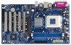
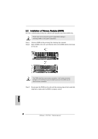
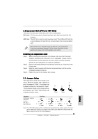
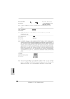
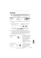
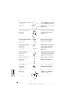
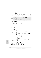
2.3 Expansion Slots (PCI and AGP Slots) There are 5 PCI slots and 1 AGP slot on K7VT6-C motherboard. PCI slots: PCI slots are used to install expansion cards that have the 32-bit PCI interface. AGP slot: The AGP slot is used to install a graphics card. The ASRock AGP slot has a special design of clasp that can securely fasten the inserted graphics card. Please do NOT use a 3.3V AGP card on the AGP slot of this motherboard! It may cause permanent damage! For the voltage information of your graphics card, please check with the graphics card vendors. Installing an expansion card Step 1. Before installing the expansion card, please make sure that the power supply is switched off or the power cord is unplugged. Please read the documentation of the expansion card and make necessary hardware settings for the card before you start the installation. Step 2. Remove the bracket facing the slot that you intend to use. Keep the screw for later use. Step 3. Align the card connector with the slot and press firmly until the card is completely seated on the slot. Step 4. Fasten the card to the chassis with screws. English 2.4 Jumpers Setup The illustration shows how jumpers are setup. When the jumper cap is placed on pins, the jumper is "Short". If no jumper cap is placed on the pins, the jumper is "Open". The illustration shows a 3-pin jumper whose pin1 and pin2 are "Short" when jumper cap is placed on these 2 pins. Short Open Jumper FSB Select Jumpers (FSB_SEL0, FSB_SEL1, FSB_SEL2) (see p.2 item 10) Setting Note: The CPU FSB frequency of this motherboard is determined by jumper-setting. You must adjust "FSB Select Jumpers" according to the FSB of your AMD CPU. Please follow the figures above to set the CPU FSB frequency. 9 ASRock K7VT6-C Motherboard
-
 1
1 -
2
-
3
-
 4
4 -
 5
5 -
 6
6 -
 7
7 -
 8
8 -
 9
9 -
 10
10 -
 11
11 -
 12
12 -
 13
13 -
 14
14 -
15
-
16
-
17
-
18
-
19
-
20
-
21
-
22
-
23
-
24
-
25
-
26
-
27
-
28
-
29
-
30
-
31
-
32
-
33
-
34
-
35
-
36
-
37
-
38
-
39
-
40
-
41
-
42
-
43
-
44
-
45
-
46
-
47
-
48
-
49
-
50
-
51
-
52
-
53
-
54
-
55
-
56
-
57
-
58
-
59
-
60
-
61
-
62
-
63
-
64
-
65
-
66
-
67
-
68
-
69
-
70
-
71
-
72
 |
 |
