ASRock N68C-GS FX User Manual - Page 21
Jumpers Setup - no display
 |
View all ASRock N68C-GS FX manuals
Add to My Manuals
Save this manual to your list of manuals |
Page 21 highlights
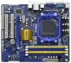
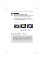
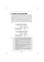
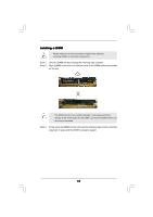
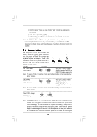
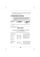
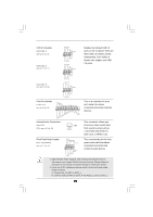
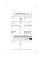
B. Click the items "This is my main monitor" and "Extend the desktop onto this monitor". C. Click "OK" to save your change. D. Repeat steps A through C for the display icon identified by the number one, two and three. 6. Use Multi Monitor feature. Click and drag the display icons to positions representing the physical setup of your monitors that you would like to use. The placement of display icons determines how you move items from one monitor to another. 2.6 Jumpers Setup The illustration shows how jumpers are setup. When the jumper cap is placed on pins, the jumper is "Short". If no jumper cap is placed on pins, the jumper is "Open". The illustration shows a 3-pin jumper whose pin1 and pin2 are "Short" when jumper cap is placed on these 2 pins. Jumper Setting PS2_USB_PWR1 (see p.12, No. 1) 1_2 +5V 2_3 +5VSB Short pin2, pin3 to enable +5VSB (standby) for PS/2 or USB01/23 wake up events. Note: To select +5VSB, it requires 2 Amp and higher standby current provided by power supply. USB_PWR2 1_2 2_3 Short pin2, pin3 to enable (see p.12, No. 15) +5V +5VSB +5VSB (standby) for USB4_5/6_7/8_9 wake up events. Note: To select +5VSB, it requires 2 Amp and higher standby current provided by power supply. Clear CMOS Jumper (CLRCMOS1) (see p.12, No. 22) 1_2 2_3 Default Clear CMOS Note: CLRCMOS1 allows you to clear the data in CMOS. The data in CMOS includes system setup information such as system password, date, time, and system setup parameters. To clear and reset the system parameters to default setup, please turn off the computer and unplug the power cord from the power supply. After waiting for 15 seconds, use a jumper cap to short pin2 and pin3 on CLRCMOS1 for 5 seconds. However, please do not clear the CMOS right 21
-
 1
1 -
2
-
3
-
4
-
5
-
6
-
7
-
8
-
9
-
10
-
11
-
12
-
13
-
14
-
15
-
 16
16 -
 17
17 -
 18
18 -
 19
19 -
 20
20 -
 21
21 -
 22
22 -
 23
23 -
 24
24 -
 25
25 -
 26
26 -
27
-
28
-
29
-
30
-
31
-
32
-
33
-
34
-
35
-
36
-
37
-
38
-
39
-
40
-
41
-
42
-
43
-
44
-
45
-
46
-
47
-
48
-
49
-
50
-
51
-
52
-
53
-
54
 |
 |