ASRock N68C-GS FX User Manual - Page 22
Onboard Headers and Connectors - no boot
 |
View all ASRock N68C-GS FX manuals
Add to My Manuals
Save this manual to your list of manuals |
Page 22 highlights
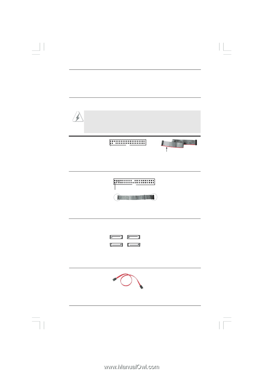
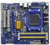
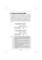
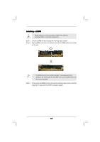
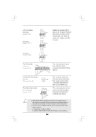
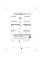
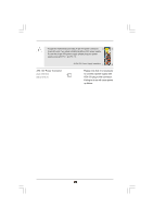
after you update the BIOS. If you need to clear the CMOS when you just finish updating the BIOS, you must boot up the system first, and then shut it down before you do the clear-CMOS action. 2.7 Onboard Headers and Connectors Onboard headers and connectors are NOT jumpers. Do NOT place jumper caps over these headers and connectors. Placing jumper caps over the headers and connectors will cause permanent damage of the motherboard! • Floppy Connector (33-pin FLOPPY1) (see p.12 No. 24) Pin1 FLOPPY1 the red-striped side to Pin1 Note: Make sure the red-striped side of the cable is plugged into Pin1 side of the connector. Primary IDE connector (Blue) (39-pin IDE1, see p.12 No. 9) PIN1 IDE1 connect the blue end to the motherboard connect the black end to the IDE devices 80-conductor ATA 66/100/133 cable Note: Please refer to the instruction of your IDE device vendor for the details. Serial ATAII Connectors (SATAII_1 (PORT 0.0): see p.12, No. 10) (SATAII_2 (PORT 0.1): see p.12, No. 13) (SATAII_3 (PORT 1.0): see p.12, No. 11) (SATAII_4 (PORT 1.1): see p.12, No. 12) SATAII_1 SATAII_3 (PORT 0.0) (PORT 1.0) SATAII_2 SATAII_4 (PORT 0.1) (PORT 1.1) Serial ATA (SATA) Data Cable (Optional) These four Serial ATAII (SATAII) connectors support SATAII or SATA hard disk for internal storage devices. The current SATAII interface allows up to 3.0 Gb/s data transfer rate. Either end of the SATA data cable can be connected to the SATA / SATAII hard disk or the SATAII connector on the motherboard. 22
-
 1
1 -
2
-
3
-
4
-
5
-
6
-
7
-
8
-
9
-
10
-
11
-
12
-
13
-
14
-
15
-
16
-
 17
17 -
 18
18 -
 19
19 -
 20
20 -
 21
21 -
 22
22 -
 23
23 -
 24
24 -
 25
25 -
 26
26 -
 27
27 -
28
-
29
-
30
-
31
-
32
-
33
-
34
-
35
-
36
-
37
-
38
-
39
-
40
-
41
-
42
-
43
-
44
-
45
-
46
-
47
-
48
-
49
-
50
-
51
-
52
-
53
-
54
 |
 |