ASRock P43DE3 User Manual
ASRock P43DE3 Manual
 |
View all ASRock P43DE3 manuals
Add to My Manuals
Save this manual to your list of manuals |
ASRock P43DE3 manual content summary:
- ASRock P43DE3 | User Manual - Page 1
P43DE3 User Manual Version 1.0 Published July 2009 Copyright©2009 ASRock INC. All rights reserved. 1 - ASRock P43DE3 | User Manual - Page 2
without written consent of ASRock Inc. Products and corporate names appearing in this manual may or may not be intent to infringe. Disclaimer: Specifications and information contained in this manual are furnished for informational use battery adopted on this motherboard contains Perchlorate, a toxic - ASRock P43DE3 | User Manual - Page 3
Windows® VistaTM / VistaTM 64-bit Without RAID Functions 32 2.16 Untied Overclocking Technology 33 3 BIOS SETUP UTILITY 34 3.1 Introduction 34 3.1.1 BIOS Menu Bar 34 3.1.2 Navigation Keys 35 3.2 Main Screen 35 3.3 OC Tweaker Screen 36 3.4 Advanced Screen 46 3.4.1 CPU Configuration - ASRock P43DE3 | User Manual - Page 4
Floppy Configuration 54 3.4.7 Super IO Configuration 54 3.4.8 USB Configuration 55 3.5 Hardware Health Event Monitoring Screen 56 Screen 59 4 Software Support 60 4.1 Install Operating System 60 4.2 Support CD Information 60 4.2.1 Running Support CD 60 4.2.2 Drivers Menu 60 4.2.3 Utilities - ASRock P43DE3 | User Manual - Page 5
guide to BIOS setup and information of the Support CD. Because the motherboard specifications and the BIOS software might be updated, the content of this manual will be subject to change without notice. In case any modifications of this manual occur, the updated version will be available on ASRock - ASRock P43DE3 | User Manual - Page 6
1.2 Specifications Platform CPU Chipset Memory Expansion Slot Audio LAN Rear Panel I/O Connector - ATX Form Factor: 12.0-in x 8.0-in, 30.5 cm x 20.3 cm - LGA 775 for Intel® CoreTM 2 Extreme / CoreTM 2 Quad / CoreTM 2 Duo / Pentium® Dual Core / Celeron® Dual Core / Celeron®, supporting Penryn Quad - ASRock P43DE3 | User Manual - Page 7
Overclocking Technology) - Supports Smart BIOS Support CD - Drivers, Utilities, AntiVirus Software (Trial Version) Unique Feature - ASRock OC Tuner (see CAUTION 10) - Intelligent Energy Saver (see CAUTION 11) - Instant Boot - ASRock Instant Flash (see CAUTION 12) - Hybrid Booster: - CPU - ASRock P43DE3 | User Manual - Page 8
memory size may be less than 4GB for the reservation for system usage under Windows® XP and Windows® VistaTM. For Windows® XP 64-bit and Windows® VistaTM 64-bit with 64-bit CPU, there is no such limitation. 7. For microphone input, this motherboard supports both stereo and mono modes. For audio - ASRock P43DE3 | User Manual - Page 9
MS-DOS or Windows®. With this utility, you can press key during the POST or press key to BIOS setup menu to access ASRock Instant Flash. Just launch this tool and save the new BIOS file to your USB flash drive, floppy disk or hard drive, then you can update your BIOS only in a few - ASRock P43DE3 | User Manual - Page 10
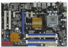
, 240-pin module) USB 2.0 T: USB4 B: USB5 Top: RJ-45 Top: SIDE SPK Center: REAR SPK Bottom: CTR BASS 37 LAN PHY 36 Intel P43 Top: LINE IN Center: FRONT Bottom: MIC IN Chipset CD1 35 PWR_FAN1 34 PCIE1 33 AUDIO CODEC PCIE2 HD_AUDIO1 32 1 PCI Express 2.0 P43DE3 FSB1600 8 CHA_FAN1 - ASRock P43DE3 | User Manual - Page 11
Speaker (Lime) 8 Microphone (Pink) 9 USB 2.0 Ports (USB45) 10 USB 2.0 Ports (USB23) 11 USB 2.0 Ports (USB01) 12 Optical SPDIF Out Port in accordance with the type of speaker you use. TABLE for Audio Output Connection Audio Output Channels Front Speaker Rear Speaker Central / Bass Side Speaker ( - ASRock P43DE3 | User Manual - Page 12
header. After restarting your computer, you will find "VIA HD Audio Deck" tool on your system. Please follow below instructions according to the OS you install. For Windows® 2000 / XP / XP 64-bit OS: Please click "VIA HD Audio Deck" icon , and click "Speaker". Then you are allowed to select - ASRock P43DE3 | User Manual - Page 13
Installation This is an ATX form factor (12.0" x 8.0", 30.5 x 20.3 cm) motherboard. Before you install the motherboard, study the configuration of your chassis to ensure that the motherboard fits into it. Make sure to unplug the power cord before installing or removing the motherboard. Failure to do - ASRock P43DE3 | User Manual - Page 14
Installation For the installation of Intel 775-LAND CPU, please follow the steps below. 775-Pin Socket Overview Before you insert the 775-LAND CPU into the socket, please check if the CPU surface is unclean or if there is any bent pin on the socket. Do not force to insert the CPU into the socket if - ASRock P43DE3 | User Manual - Page 15
CPU is within the socket and properly mated to the orient keys. Step 3. Remove PnP Cap (Pick and Place Cap): Use your left hand index finger and thumb to support PnP cap. 2. This cap must be placed if returning the motherboard for after service. Step 4. Close the socket: Step 4-1. Rotate the load - ASRock P43DE3 | User Manual - Page 16
Heatsink This motherboard is equipped with 775-Pin socket that supports Intel 775-LAND CPU. Please adopt the type of heatsink and cooling fan compliant with Intel 775-LAND CPU to dissipate heat. Before you installed the heatsink, you need to spray thermal interface material between the CPU and the - ASRock P43DE3 | User Manual - Page 17
DDR3_A1 and DDR3_A2, it is unable to activate the Dual Channel Memory Technology . 4. It is not allowed to install a DDR or DDR2 memory module into DDR3 slot;otherwise, this motherboard and DIMM may be damaged. 5. If you adopt a DDR3 1600 memory module, you can only install it on DDR3_A1 slot. 17 - ASRock P43DE3 | User Manual - Page 18
matches the break on the slot. notch break notch break The DIMM only fits in one correct orientation. It will cause permanent damage to the motherboard and the DIMM if you force the DIMM into the slot at incorrect orientation. Step 3. Firmly insert the DIMM into the slot until the retaining - ASRock P43DE3 | User Manual - Page 19
the expansion card and make necessary hardware settings for the card before you start the installation. Step 2. Remove the system unit cover (if your motherboard is already installed in a chassis). Step 3. Remove the bracket facing the slot that you intend to use. Keep the screws for later use. Step - ASRock P43DE3 | User Manual - Page 20
Setting Description PS2_USB_PWR1 (see p.10 No. 1) 1_2 +5V 2_3 +5VSB Short pin2, pin3 to enable +5VSB (standby) for PS/2 or USB wake up events. Note: clear the CMOS right after you update the BIOS. If you need to clear the CMOS when you just finish updating the BIOS, you must boot up the system - ASRock P43DE3 | User Manual - Page 21
connector. Primary IDE connector (Blue) (39-pin IDE1, see p.10 No. 9) PIN1 IDE1 connect the blue end to the motherboard connect the black end to the IDE devices 80-conductor ATA 66/100/133 cable Note: Please refer to the instruction of your IDE device vendor for the details. Serial ATAII - ASRock P43DE3 | User Manual - Page 22
p.10 No. 35) IRTX +5V DUMMY 1 GND IRRX CD-L GND GND CD-R CD1 PCICLK FRAME PCIRST# LAD3 +3V LAD0 NC +3VSB GND PWRDWN GND NC LAD2 LAD1 GND NC SERIRQ CLKRUN NC Besides six default USB 2.0 ports on the I/O panel, there are three USB 2.0 headers on this motherboard. Each USB 2.0 header can support - ASRock P43DE3 | User Manual - Page 23
cable that allows convenient connection and control of audio devices. 1. High Definition Audio supports Jack Sensing, but the panel wire on the chassis must support HDA to function correctly. Please follow the instruction in our manual and chassis manual to install your system. 2. If you use AC - ASRock P43DE3 | User Manual - Page 24
fan (Quiet Fan) support, the 3-Pin CPU fan still can work successfully even without the fan speed control function. If you plan to connect the 3-Pin CPU fan to the CPU fan connector on this motherboard, please connect it to Pin 1-3. Pin 1-3 Connected 3-Pin Fan Installation ATX Power Connector (24 - ASRock P43DE3 | User Manual - Page 25
providing SPDIF audio output to HDMI VGA card, allows the system to connect HDMI Digital TV/ projector/LCD devices. Please connect the HDMI_SPDIF connector of HDMI VGA card to this header. Please connect the black end (A) of HDMI_SPDIF cable to the HDMI_SPDIF header on the motherboard. Then connect - ASRock P43DE3 | User Manual - Page 26
. For the proper installation of HDMI VGA card, please refer to the installation guide on page 19. Step 2. Connect the black end (A) of HDMI_SPDIF cable to the HDMI_SPDIF header (HDMI_SPDIF1, yellow, see page 10, No. 27) on the motherboard. Make sure to correctly connect the HDMI_SPDIF cable to the - ASRock P43DE3 | User Manual - Page 27
guide. Some default setting of SATAII hard disks may not be at SATAII mode, which operate with the best performance. In order to enable SATAII function, please follow the below instruction 's website for details: http://www.hitachigst.com/hdd/support/download.htm The above examples are just for your - ASRock P43DE3 | User Manual - Page 28
Serial ATAII (SATAII) Hard Disks Installation P43DE3 adopts Intel® ICH10 south bridge chipset that supports Serial ATA (SATA) / Serial ATAII (SATAII) hard disks. You may install SATA / SATAII hard disks on this motherboard for internal storage devices. This section will guide you to install the SATA - ASRock P43DE3 | User Manual - Page 29
SATA / SATAII Hot Plug support information of our motherboard is indicated in the product spec on our website: www.asrock.com 2. Make sure your SATA / SATAII HDD can support Hot Plug function from your dealer or HDD user manual. The SATA / SATAII HDD, which cannot support Hot Plug function, will be - ASRock P43DE3 | User Manual - Page 30
cable to (White) to the power supply 1x4-pin cable. the motherboard's SATAII connector. SATA power cable 1x4-pin power connector (White) Step attention, before you process the Hot Unplug: Please do follow below instruction sequence to process the Hot Unplug, improper procedure will cause the SATA - ASRock P43DE3 | User Manual - Page 31
procedures according to the OS you install. Since Windows® 2000 AHCI driver is not provided by the chipset vendor, AHCI function is not supported under Windows® 2000. 2.15.1 Installing Windows® 2000 / XP / XP 64-bit Without RAID Functions If you want to install Windows® 2000 / XP / XP 64-bit OS on - ASRock P43DE3 | User Manual - Page 32
the instruction to install Windows® VistaTM / VistaTM 64-bit OS on your system. When you see "Where do you want to install Windows?" page, please insert the ASRock Support CD into your optical drive, and click the "Load Driver" button on the left on the bottom to load the Intel® AHCI drivers. Intel - ASRock P43DE3 | User Manual - Page 33
Technology This motherboard supports Untied Overclocking Technology, which means during overclocking, FSB enjoys better margin due to fixed PCI / PCIE buses. Before you enable Untied Overclocking function, please enter "Overclock Mode" option of BIOS setup to set the selection from [Auto] to [Manual - ASRock P43DE3 | User Manual - Page 34
BIOS SETUP UTILITY to configure your system. The BIOS FWH chip on the motherboard stores the BIOS SETUP UTILITY. You may run the BIOS Because the BIOS software is constantly being updated, the following BIOS setup screens OC Tweaker To set up overclocking features Advanced To set up the advanced BIOS - ASRock P43DE3 | User Manual - Page 35
29/2009] BIOS Version : P43DE3 P1.00 Processor Type : Intel (R) Core (TM) 2 Duo CPU E8400 @ 3.00GHz (64bit) Processor Speed : 4400MHz Microcode Update : 1067A/A07 Cache Size : 6144KB Total Memory DDR3_A1 DDR3_A2 DDR3_B1 DDR3_B2 : 2048MB Single-Channel Memory Mode : 2048MB/550MHz (DDR3 1100 - ASRock P43DE3 | User Manual - Page 36
CPU EZ OC Setting You can use this option to load CPU EZ overclocking setting. Configuration options: [CPU 3.00GHz], [CPU 3.20GHz], [CPU 3.40GHz], [CPU 3.60GHz], [CPU 3.80GHz], [CPU 4.00GHz], [CPU 4.20GHz] and [CPU 4.40GHz]. Please note that overclocing may cause damage to your CPU and motherboard - ASRock P43DE3 | User Manual - Page 37
the ratio value of this motherboard. DRAM Frequency If [Auto] is selected, the motherboard will detect the memory module(s) inserted and assigns appropriate frequency automatically. You may select [Auto], [533MHz (DDR3 1066)], [667MHz (DDR3 1333)] or [800MHz (DDR3 1600)]. DRAM Command Rate Use - ASRock P43DE3 | User Manual - Page 38
DRAM Timing Configuation BIOS SETUP UTILITY OC Tweaker Standard Memory Settings XMP Technology [Auto] Profile 1 : DDR3 2000 7-8-7-20 1.65V Standard Memory Settings : 7-8-7-20-78-10-8-7-8 DRAM tCL [Auto] DRAM tRCD [Auto] DRAM tRP [Auto] DRAM tRAS [Auto] DRAM tRFC [Auto] DRAM tWR [ - ASRock P43DE3 | User Manual - Page 39
DRAM tRTP This controls the number of DRAM clocks for TRTP. Min: 2. Max: 13. The default value is [Auto]. 39 - ASRock P43DE3 | User Manual - Page 40
DRAM RCOMP and tRD Configuration BIOS SETUP UTILITY OC Tweaker DRAM RCOMP Settings DRAM CH0 RCOMP Settings : 54-0-11-6-6-6-6 DRAM CH0 RCOMP ODT DRAM CH0 G0 (Data) DRAM CH0 G1 (Command) [Auto] [Auto] [Auto] - ASRock P43DE3 | User Manual - Page 41
DRAM CH1 G1 (Command) This controls the number of DRAM CH1 G1 (Command). Min: 1. Max: 15. The default value is [Auto]. DRAM CH1 G2 (Control1) This controls the number of DRAM CH1 G2 (Control1). Min: 1. Max: 15. The default value is [Auto]. DRAM CH1 G3 (Control2) This controls the number of DRAM CH1 - ASRock P43DE3 | User Manual - Page 42
DRAM DLL SKEW Settings BIOS SETUP UTILITY OC Tweaker DRAM DLL SKEW Settings DRAM CH0 CLKSET0 SKEW DRAM CH0 CTRL1 SKEW [Auto] DRAM CH0 CTRL2 SKEW Info :10-0-0-0-0-890 DRAM CH0 CTRL2 SKEW [Auto] DRAM CH0 CTRL3 SKEW Info :10-0-0-0-0-890 DRAM CH0 CTRL3 SKEW [Auto] DRAM CH1 CLKSET0 SKEW Info - ASRock P43DE3 | User Manual - Page 43
DRAM CH1 CMD SKEW This controls the number of DRAM CH1 CMD SKEW. Configuration options: [Auto], [8] to [827]. The default value is [Auto]. DRAM CH1 CTRL0 SKEW This controls the number of DRAM CH1 CTRL0 SKEW. Configuration options: [Auto], [8] to [827]. The default value is [Auto]. DRAM CH1 CTRL1 - ASRock P43DE3 | User Manual - Page 44
Voltage Settings BIOS SETUP UTILITY OC Tweaker Voltage Settings CPU Voltage DRAM Voltage GTLRef Voltage NB Voltage NB GTL Ref. Voltage SB Core Voltage SB 1.1V Voltage VTT Voltage PLL Voltage [Auto] [Auto] [Auto] [Auto] [Auto] [Auto] [Auto] [Auto] [Auto] Options Auto Manual Overdrive Offset +F1 - ASRock P43DE3 | User Manual - Page 45
VDrop Control Use this to enable or disable ASRock VDrop control. Configuration options: [With VDrop] and [Without VDrop]. The default value is [With VDrop]. Would you like to save current setting user defaults? In - ASRock P43DE3 | User Manual - Page 46
. ASRock Instant Flash ASRock Instant Flash is a BIOS flash utility embedded in Flash ROM. This convenient BIOS update tool allows you to update system BIOS without entering operating systems first like MS-DOS or Windows®. Just launch this tool and save the new BIOS file to your USB flash - ASRock P43DE3 | User Manual - Page 47
be hidden if the installed CPU does not support Intel (R) Virtualization Technology. CPU Thermal Throttling You may select [Enabled] to enable P4 CPU internal thermal control mechanism to keep the CPU from overheated. No-Excute Memory Protection No-Execution (NX) Memory Protection Technology is an - ASRock P43DE3 | User Manual - Page 48
this item to [Enabled]. This item will be hidden if the current CPU does not support Intel (R) SpeedStep(tm) tech.. Please note that enabling this function may reduce CPU voltage and lead to system stability or compatibility issue with some power supplies. Please set this item to [Disable] if above - ASRock P43DE3 | User Manual - Page 49
3.4.2 Chipset Configuration BIOS SETUP UTILITY Advanced Chipset Settings Intelligent Energy Saver Primary Graphics Adapter Onboard HD Audio Front Panel OnBoard Lan CIR10 Field 1 [Disabled] [PCI] [Auto] [Enabled] [Enabled] [Enabled] Options Disabled Enabled +F1 F9 F10 ESC Select Screen Select - ASRock P43DE3 | User Manual - Page 50
3.4.3 ACPI Configuration BIOS SETUP UTILITY Advanced ACPI Configuration Suspend To RAM Restore on AC/Power Loss Ring-In Power On PCI Devices Power On PS / 2 Keyboard Power On RTC Alarm Power On EUP Support ACPI HPET Table [Disabled] [Power Off] [Disabled] [Disabled] [Disabled] [Disabled] [Auto] [ - ASRock P43DE3 | User Manual - Page 51
plan to use this motherboard to submit Windows® VistaTM certification. 3.4.4 Storage Configuration BIOS SETUP UTILITY Advanced default value is [Enabled]. AHCI (Advanced Host Controller Interface) supports NCQ and other new features that will improve SATA disk performance instruction. 51 - ASRock P43DE3 | User Manual - Page 52
BIOS SETUP UTILITY Advanced Primary IDE Master Device Vendor Size LBA Mode Block Mode PIO Mode Async DMA Ultra DMA S.M.A.R.T. Type LBA/Large Mode Block (Multi-Sector Transfer) PIO Mode DMA Mode S.M.A.R.T. 32Bit Data Transfer :Hard Disk :ST340014A :40.0 GB :Supported DOS and Windows; for Netware - ASRock P43DE3 | User Manual - Page 53
Configuration options: [0], [5], [10], [15], [20], [25], [30] and [35]. The default value is [35]. 3.4.5 PCIPnP Configuration BIOS SETUP UTILITY Advanced Advanced default value unless the installed PCI expansion cards' specifications require other settings. PCI IDE BusMaster Use this item to - ASRock P43DE3 | User Manual - Page 54
SETUP UTILITY Advanced Configure Super IO Chipset OnBoard Floppy Controller Serial Port Address Infrared Port Address [Enabled] [3F8 / IRQ4] [Disabled] Allow BIOS to Enable or Disable Floppy Controller. +F1 F9 F10 ESC Select Screen Select Item Change Option General Help Load Defaults Save and - ASRock P43DE3 | User Manual - Page 55
these four options: [Enabled] - Enables support for legacy USB. [Auto] - Enables legacy support if USB devices are connected. [Disabled] - USB devices are not allowed to use under legacy OS and BIOS setup when [Disabled] is selected. If you have USB compatibility issue, it is recommended to select - ASRock P43DE3 | User Manual - Page 56
to monitor the status of the hardware on your system, including the parameters of the CPU temperature, motherboard temperature, CPU fan speed, chassis fan speed, and the critical voltage. BIOS SETUP UTILITY Main OC Tweaker Advanced H/W Monitor Boot Security Exit Hardware Health Event Monitoring - ASRock P43DE3 | User Manual - Page 57
, it will display the available devices on your system for you to configure the boot settings and the boot priority. BIOS SETUP UTILITY Main OC Tweaker Advanced H/W Monitor Boot Security Exit Boot Settings Boot Settings Configuration Configure Settings during System Boot. 1st Boot Device 2nd - ASRock P43DE3 | User Manual - Page 58
option "Full Screen Logo". Configuration options: [Auto], [EuP], [Scenery] and [ASRock]. The default value is [Auto]. Boot From Onboard LAN Use this item to enable the user password, you may also clear it. BIOS SETUP UTILITY Main OC Tweaker Advanced H/W Monitor Boot Security Exit Security Settings - ASRock P43DE3 | User Manual - Page 59
3.8 Exit Screen BIOS SETUP UTILITY Main OC Tweaker Advanced H/W Monitor Boot Security Exit Exit Options Save Changes and Exit Discard Changes and Exit Discard Changes Load BIOS Defaults Load Performance Setup Default (IDE/SATA) Load Performance Setup AHCI Mode Load Power Saving Setup Default Exit - ASRock P43DE3 | User Manual - Page 60
that the motherboard supports. Click on a specific item then follow the installation wizard to install it. 4.2.4 Contact Information If you need to contact ASRock or want to know more about ASRock, welcome to visit ASRock's website at http://www.asrock.com; or you may contact your dealer for further
-
 1
1 -
 2
2 -
 3
3 -
 4
4 -
 5
5 -
 6
6 -
 7
7 -
8
-
9
-
10
-
11
-
12
-
13
-
14
-
15
-
16
-
17
-
18
-
19
-
20
-
21
-
22
-
23
-
24
-
25
-
26
-
27
-
28
-
29
-
30
-
31
-
32
-
33
-
34
-
35
-
36
-
37
-
38
-
39
-
40
-
41
-
42
-
43
-
44
-
45
-
46
-
47
-
48
-
49
-
50
-
51
-
52
-
53
-
54
-
55
-
56
-
57
-
58
-
59
-
60
 |
 |

1
P43DE3
User Manual
Version 1.0
Published July 2009
Copyright©2009 ASRock INC. All rights reserved.