ASRock P43DE3 User Manual - Page 10
Intel, Chipset - ddr3
 |
View all ASRock P43DE3 manuals
Add to My Manuals
Save this manual to your list of manuals |
Page 10 highlights
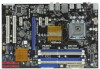
1.3 Motherboard Layout 1 2 34 56 20.3cm (8.0 in) PS2 Mouse PS2 Keyboard 1 PS2_USB_PWR1 ATX12V1 CPU_FAN1 Coaxial SPDIF Optical SPDIF DDR3_B1 (64 bit, 240-pin module) DDR3_B2 (64 bit, 240-pin module) AT X P W R 1 DDR3 1600 Dual Channel USB 2.0 T: USB0 B: USB1 7 USB 2.0 T: USB2 B: USB3 DDR3_A2 (64 bit, 240-pin module) DDR3_A1 (64 bit, 240-pin module) USB 2.0 T: USB4 B: USB5 Top: RJ-45 Top: SIDE SPK Center: REAR SPK Bottom: CTR BASS 37 LAN PHY 36 Intel P43 Top: LINE IN Center: FRONT Bottom: MIC IN Chipset CD1 35 PWR_FAN1 34 PCIE1 33 AUDIO CODEC PCIE2 HD_AUDIO1 32 1 PCI Express 2.0 P43DE3 FSB1600 8 CHA_FAN1 IDE1 9 30.5cm (12.0 in) 31 30 29 28 27 EuP Ready PCIE3 Super I/O RoHS IR1 1 HDMI_SPDIF1 1 FLOPPY1 PCIE4 CMOS Battery PCI1 1 CLRCMOS1 PCI2 COM1 1 1 TPM1 8Mb BIOS Intel ICH10 USB10_11 1 SPEAKER1 1 PLED PWRBTN PANEL1 1 HDLED RESET USB8_9 1 USB6_7 1 SATAII_5 (Port 4) SATAII_3 (Port 2) SATAII_1 (Port 0) SATAII_6 (Port 5) SATAII_4 (Port 3) SATAII_2 (Port 1) 10 11 12 13 14 15 16 26 25 24 23 22 21 20 19 18 17 1 PS2_USB_PWR1 Jumper 20 USB 2.0 Header (USB8_9, Blue) 2 ATX 12V Connector (ATX12V1) 21 USB 2.0 Header (USB10_11, Blue) 3 CPU Fan Connector (CPU_FAN1) 22 System Panel Header (PANEL1, Orange) 4 775-Pin CPU Socket 23 Chassis Speaker Header 5 2 x 240-pin DDR3 DIMM Slots (SPEAKER 1, Purple) (Dual Channel: DDR3_A1, DDR3_B1; Blue) 24 TPM Header (TPM1) 6 2 x 240-pin DDR3 DIMM Slots 25 COM Port Header (COM1) (Dual Channel: DDR3_A2, DDR3_B2; White) 26 Floppy Connector (FLOPPY1) 7 ATX Power Connector (ATXPWR1) 27 HDMI_SPDIF Header 8 Chassis Fan Connector (CHA_FAN1) (HDMI_SPDIF1, Yellow) 9 IDE1 Connector (IDE1, Blue) 28 Infrared Module Header (IR1) 10 Clear CMOS Jumper (CLRCMOS1) 29 PCI Slots (PCI1 - 2) 11 SPI BIOS Chip 30 PCI Express x1 Slot (PCIE4) 12 South Bridge Controller 31 PCI Express 2.0 x16 Slot (PCIE3, Blue) 13 Primary SATAII Connector (SATAII_1 (Port 0), Red) 32 Front Panel Audio Header 14 Secondary SATAII Connector (SATAII_2 (Port 1), Red) (HD_AUDIO1, Lime) 15 Third SATAII Connector (SATAII_3 (Port 2), Red) ) 33 PCI Express x1 Slot (PCIE2) 16 Fourth SATAII Connector (SATAII_4 (Port 3), Red) 34 PCI Express x1 Slot (PCIE1) 17 Sixth SATAII Connector (SATAII_6 (Port 5), Red) 35 Internal Audio Connector: CD1 (Black) 18 Fifth SATAII Connector (SATAII_5 (Port 4), Red) 36 Power Fan Connector (PWR_FAN1) 19 USB 2.0 Header (USB6_7, Blue) 37 North Bridge Controller 10
-
 1
1 -
2
-
3
-
4
-
 5
5 -
 6
6 -
 7
7 -
 8
8 -
 9
9 -
 10
10 -
 11
11 -
 12
12 -
 13
13 -
 14
14 -
 15
15 -
16
-
17
-
18
-
19
-
20
-
21
-
22
-
23
-
24
-
25
-
26
-
27
-
28
-
29
-
30
-
31
-
32
-
33
-
34
-
35
-
36
-
37
-
38
-
39
-
40
-
41
-
42
-
43
-
44
-
45
-
46
-
47
-
48
-
49
-
50
-
51
-
52
-
53
-
54
-
55
-
56
-
57
-
58
-
59
-
60
 |
 |
