ASRock P4VM800 User Manual
ASRock P4VM800 Manual
 |
View all ASRock P4VM800 manuals
Add to My Manuals
Save this manual to your list of manuals |
ASRock P4VM800 manual content summary:
- ASRock P4VM800 | User Manual - Page 1
P4VM800 User Manual Version 1.0 Published April 2005 Copyright©2005 ASRock INC. All rights reserved. 1 - ASRock P4VM800 | User Manual - Page 2
backup purpose, without written consent of ASRock Inc. Products and corporate names appearing in this manual may or may not be registered trademarks benefit, without intent to infringe. Disclaimer: Specifications and information contained in this manual are furnished for informational use only and - ASRock P4VM800 | User Manual - Page 3
Contents 5 1.2 Specifications 6 1.3 Motherboard Layout 8 1.4 ASRock I/O Plus 9 TM 2. Installation 10 Pre-installation Precautions 10 2.1 CPU Installation 11 2.2 Installation of CPU Fan and Heatsink 11 2.3 Installation of Memory Modules (DIMM 12 2.4 Expansion Slots (PCI, AMR, and AGP Slots - ASRock P4VM800 | User Manual - Page 4
4. Software Support 35 4.1 Install Operating System 35 4.2 Support CD Information 35 4.2.1 Running Support CD 35 4.2.2 Drivers Menu 35 4.2.3 Utilities Menu 35 4.2.4 Contact Information 35 4 - ASRock P4VM800 | User Manual - Page 5
any modifications of this manual occur, the updated version will be available on ASRock website without further notice. You may find the latest memory and CPU support lists on ASRock website as well. ASRock website http://www.asrock.com 1.1 Package Contents ASRock P4VM800 Motherboard (Micro ATX Form - ASRock P4VM800 | User Manual - Page 6
Socket 478, supports Intel® Pentium® 4 / Celeron® (Prescott, Northwood, Willimate) processor Chipsets: North Bridge: VIA P4M800 CE, FSB @ 800/533/400 MHz, with Intel® Hyper-Threading Technology ready (see CAUTION 1) South Bridge: VIA VT8237R, supports USB 2.0, ATA 133, SATA 1.5Gb/s Memory - ASRock P4VM800 | User Manual - Page 7
remember to spray thermal grease between the CPU and the heatsink when you install the PC system. 3. Do NOT use a 3.3V AGP card on the AGP slot of this motherboard! It may cause permanent damage! 4. Power Management for USB 2.0 works fine under Microsoft® Windows® XP SP1 / 2000 SP4. It may not work - ASRock P4VM800 | User Manual - Page 8
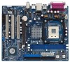
VIA P4M800 Chipset 5.1CH 1 AUDIO1 CMOS Battery JR1 JL1 CLRCMOS1 CD1 AUX1 Audio CODEC AMR1 AGP 8X 1.5V_AGP1 ATA133 IDE1 IDE2 PCI 1 ` P4VM800 PCI 2 USB2.0 PCI 3 1 COM1 VIA VT8237R SATA 1 USB67 PANEL 1 PLED PWRBTN 1 1 SPEAKER1 HDLED RESET SATA2 SATA1 Prescott 800 DDR400 DDR1 (64 - ASRock P4VM800 | User Manual - Page 9
1.4 ASRock I/O PlusTM 1 11 10 9 1 Parallel Port 2 RJ-45 Port 3 Line In (Light Blue) 4 Line Out (Lime) 5 Microphone (Pink) 6 Shared USB 2.0 Ports (USB45) 2 3 4 5 8 7 6 7 USB 2.0 Ports (USB01) 8 USB 2.0 Ports (USB23) 9 VGA Port 10 PS/2 Keyboard Port (Purple) 11 PS/2 Mouse Port (Green) 9 - ASRock P4VM800 | User Manual - Page 10
Precautions Take note of the following precautions before you install motherboard components or change any motherboard settings. 1. Unplug the power cord from the wall socket before touching any component. 2. To avoid damaging the motherboard components due to static electricity, NEVER place your - ASRock P4VM800 | User Manual - Page 11
to 90° STEP 2/STEP 3: Match The CPU Marked Corner to The Socket Marked Corner STEP 4: Push Down And Lock The Socket Lever 2.2 Installation of CPU Fan and Heatsink This motherboard adopts 478-pin CPU socket to support Intel® Pentium® 4 / Celeron® CPU. It requires larger heatsink and cooling fan - ASRock P4VM800 | User Manual - Page 12
2.3 Installation of Memory Modules (DIMM) P4VM800 motherboard provides two 184-pin DDR (Double Data Rate) DIMM slots. Please make sure to disconnect power supply before adding or removing DIMMs or the system components. Step 1. Unlock a DIMM slot by pressing the retaining clips outward. Step 2. - ASRock P4VM800 | User Manual - Page 13
3 PCI slots, 1 AMR slot, and 1 AGP slot on P4VM800 motherboard. PCI slots: PCI slots are used to install expansion cards that have the 32-bit PCI interface. AMR slot: The AMR slot is used to insert an ASRock MR card with v.92 Modem functionality. AGP slot: The AGP slot is used to install a graphics - ASRock P4VM800 | User Manual - Page 14
) for PS/2 or USB wake up events. Note: To select +5VSB, it requires 2 Amp and higher standby current provided by power supply. JR1(see p.8, No. 25) JL1(see p.8, No. 25) JR1 JL1 Note: If the jumpers JL1 and JR1 are short, both the front panel and the rear panel audio connectors can work. Clear - ASRock P4VM800 | User Manual - Page 15
the IDE devices 80-conductor ATA 66/100/133 cable Note: If you use only one IDE device on this motherboard, please set the IDE device as "Master". Please refer to the instruction of your IDE device vendor for the details. Besides, to optimize compatibility and performance, please connect your hard - ASRock P4VM800 | User Manual - Page 16
the black end of SATA power cable to the power connector on the drive. Then connect the white end of SATA power cable to the power connector of the power supply. USB 2.0 Header (9-pin USB67) (see p.8, No. 18) USB_PWR P-7 P+7 GND DUMMY 1 GND P+6 P-6 USB_PWR ASRock I/O PlusTM provides you 6 ready - ASRock P4VM800 | User Manual - Page 17
failure to power up. Please install the heatsink and the CPU fan before installing ATX 12V connector; otherwise, it may cause permanent damage! Serial port connector (9-pin COM1) (see p.8 item 19) RRXD1 DDTR#1 DDSR#1 CCTS#1 1 RRI#1 RRTS#1 GND TTXD1 DDCD#1 17 This COM1 connector supports a serial - ASRock P4VM800 | User Manual - Page 18
Functions for SATA HDDs P4VM800 motherboard supports Hot Plug and Hot Swap functions for SATA Devices. NOTE What is Hot Plug Function? If the SATA HDDs are NOT set for RAID configuration, it is called "Hot Plug" for the action to insert and remove the SATA HDDs while the system is still power-on and - ASRock P4VM800 | User Manual - Page 19
in the Support CD, "Guide to SATA Hard Disks Installation and RAID Configuration", which is located in the folder at the following path: .. \ SATA RAID BIOS STEP 3: Install Windows 2000 / Windows XP OS on your system. After making a SATA driver diskette and using "SATA RAID BIOS" to set RAID - ASRock P4VM800 | User Manual - Page 20
the "SATA Operation Mode" option from [RAID] to [non-RAID]. STEP 2: Install Windows 98 / ME / 2000 / XP OS on your system. After setting up BIOS, you can start to install Windows 98 / ME / 2000 / XP on your system. If you don't want to set up RAID functions, there is no need to make a SATA driver - ASRock P4VM800 | User Manual - Page 21
SETUP UTILITY to configure your system. The Flash Memory on the motherboard stores the BIOS SETUP UTILITY. You may run the BIOS SETUP UTILITY when you start up the computer. Please press during the Power-On-Self-Test (POST) to enter the BIOS SETUP UTILITY, otherwise, POST will continue with its - ASRock P4VM800 | User Manual - Page 22
H/W Monitor Boot Security Exit System Overview System Time System Date [17:00:09] [Fri 02/25/2005] BIOS Version : P4VM800 BIOS P1.00 Processor Type : Intel (R) Pentium (R) 4 CPU 2.40 GHz Processor Speed : 2400 MHz Cache Size : 512KB Microcode Update : 0F24/1E Total Memory DIMM 1 DIMM - ASRock P4VM800 | User Manual - Page 23
and Exit Exit v02.54 (C) Copyright 1985-2003, American Megatrends, Inc. CPU Host Frequency While entering setup, BIOS auto detects the present CPU host frequency of this motherboard. The actual CPU host frequency will show in the following item. Boot Failure Guard Enable or disable the feature of - ASRock P4VM800 | User Manual - Page 24
for this technology, such as Microsoft® Windows® XP. Set to [Auto] if using Microsoft® Windows® XP, or Linux kernel version 2.4.18 or higher. This option will be hidden if the installed CPU does not support Hyper-Threading technology. Max CPUID Value Limit For Prescott CPU only, some OSes (ex. NT4 - ASRock P4VM800 | User Manual - Page 25
motherboard, you may select [Auto], [8X] or [4X] as the AGP mode. If the installed AGP card is a 4X-AGP card, then you may set the AGP mode as [Auto], [4X], [2X], or [1X]. AGP Fast Write This allows you to enable or disable the feature of AGP fast write protocol support. Onboard AGP Share Memory - ASRock P4VM800 | User Manual - Page 26
3.3.3 ACPI Configuration BIOS SETUP UTILITY Advanced ACPI Configuration Suspend To RAM Restore on AC / Power Loss Ring-In Power On PCI Devices Power On PS / 2 Keyboard Power On RTC Alarm Power On [Disabled] [Power Off] [Disabled] [Disabled] [Disabled] [Disabled] Select auto-detect or disable the - ASRock P4VM800 | User Manual - Page 27
you don't want to operate RAID function on SATA HDDs, please select [non-RAID]. IDE Device Configuration You may set the IDE configuration for the device that you specify. We will use the "Primary IDE Master" as the example in the following instruction, which can be applied to the configurations of - ASRock P4VM800 | User Manual - Page 28
[Auto] to automatically detect the hard disk drive. After selecting the hard disk information into BIOS, use a disk utility for a hard disk > 512 MB under DOS and Windows; for Netware and UNIX user, select [Disabled] to transfer. PIO Mode Use this item to set the PIO mode to enhance hard disk - ASRock P4VM800 | User Manual - Page 29
the installed PCI expansion cards' specifications require other settings. PCI IDE BusMaster Use this item to enable or disable the PCI IDE BusMaster feature. 3.3.6 Floppy Configuration In this section, you may configure the type of your floppy drive. BIOS - ASRock P4VM800 | User Manual - Page 30
Chipset OnBoard Floppy Controller Serial Port Address Infrared Port Address Parallel Port Address Parallel Port Mode EPP Version ECP Mode DMA Channel Parallel Port IRQ [Enabled] [3F8 / IRQ4] [Disabled] [378] [ECP + EPP] [1.9] [DMA3] [IRQ7] Allow BIOS Use this item to set the address for the - ASRock P4VM800 | User Manual - Page 31
3.3.8 USB Configuration BIOS SETUP UTILITY Advanced USB Configuration USB Controller USB 2.0 Support Legacy USB Support [Enabled] [Enabled] [Disabled] To enable or disable the onboard USB controllers. +F1 F9 F10 ESC Select Screen Select Item Change Option General Help Load Defaults Save and - ASRock P4VM800 | User Manual - Page 32
the parameters of the CPU temperature, motherboard temperature, CPU fan speed, chassis fan speed, and the critical voltage. BIOS SETUP UTILITY Main Advanced H/W Monitor Boot Security Exit Hardware Health Event Monitoring CPU Temperature M / B Temperature CPU Fan Speed Chassis Fan Speed - ASRock P4VM800 | User Manual - Page 33
Utility Use this to enable or disable VIA VT8237 SATA Raid BIOS Utility during POST. Boot Up Num-Lock If this item is set to [On], it will automatically activate the Numeric Lock function after boot-up. 3.6 Security Screen In this section, you may set or change the supervisor/user password for the - ASRock P4VM800 | User Manual - Page 34
3.7 Exit Screen Main BIOS SETUP UTILITY Advanced H/W Monitro Boot Security Exit Exit Options Save Changes and "Save configuration changes and exit setup?" Select [OK] to save the changes and exit the BIOS SETUP UTILITY. Discard Changes and Exit When you select this option, it will pop-out the - ASRock P4VM800 | User Manual - Page 35
Install Operating System This motherboard supports various Microsoft® Windows® operating systems: 98 SE / ME / 2000 / XP. Because motherboard settings and hardware options vary, use the setup procedures in this chapter for general reference only. Refer to your OS documentation for more information
-
 1
1 -
 2
2 -
 3
3 -
 4
4 -
 5
5 -
 6
6 -
 7
7 -
8
-
9
-
10
-
11
-
12
-
13
-
14
-
15
-
16
-
17
-
18
-
19
-
20
-
21
-
22
-
23
-
24
-
25
-
26
-
27
-
28
-
29
-
30
-
31
-
32
-
33
-
34
-
35
 |
 |

1
P4VM800
User Manual
Version 1.0
Published April 2005
Copyright©2005 ASRock INC. All rights reserved.