ASRock P4i45D User Manual
ASRock P4i45D Manual
 |
View all ASRock P4i45D manuals
Add to My Manuals
Save this manual to your list of manuals |
ASRock P4i45D manual content summary:
- ASRock P4i45D | User Manual - Page 1
P4I45D User Manual Published October 2002 Copyright©2002 ASRock INC. All rights reserved. 1 - ASRock P4i45D | User Manual - Page 2
backup purpose, without written consent of ASRock Inc. Products and corporate names appearing in this manual may or may not be registered trademarks benefit, without intent to infringe. Disclaimer: Specifications and information contained in this manual are furnished for informational use only and - ASRock P4i45D | User Manual - Page 3
4 1.1 Package Contents 4 1.2 Specifications 4 1.3 Motherboard Layout 6 1.4 ASRock I/OTM 7 2 Installation 8 2.1 Screw Holes 8 2.2 Pre-installation Precautions 8 2.3 CPU Installation 8 2.4 Installation of Heatsink and CPU fan 9 2.5 Installation of Memory Modules (DIMM 9 2.6 Expansion Slots - ASRock P4i45D | User Manual - Page 4
30.5 x 24.4 cm) ASRock P4I45D Quick Installation Guide ASRock Intel-Intel Series Support CD 1 Cable for IDE devices (1 x ATA 66/100) 1 Cable for floppy drive (1 x ribbon cable) 1 ASRock I/O shield 1.2 Specifications Platform: ATX form factor (12" x 9.6", 30.5 x 24.4 cm) CPU: Socket 478 for Intel - ASRock P4i45D | User Manual - Page 5
port: ECP/EPP support; Audio Jack: Line Out/ Line In/ Microphone + 1 Game port AMI legal BIOS;Supports "Plug and Play"; ACPI 1.1 compliance wake up events; Supports jumperfree; SMBIOS 2.3.1 support; CPU frequency stepless control (only for advanced users' reference, see CAUTION 5); Microsoft - ASRock P4i45D | User Manual - Page 6
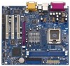
4 P4I45D 01 23 01 23 IDE2 8 Intel ICH2 16 IDE1 7 CLRCMOS1 17 FLOPPY1 10 11 2MB BIOS CMOS Battery 9 CHA_FAN1 PCI 5 USB45 (USB2.0) 1 IR1 1 SPEAKER1 1 PLED PWRBTN 1 HDLED PANEL 1 RST 15 13 14 12 1 ATX power connector (ATXPWR1) 14 Infrared module connector (IR1) 2 CPU socket - ASRock P4i45D | User Manual - Page 7
1.4 ASRock I/OTM 1 2 3 11 10 1 Parallel port 2 RJ-45 port 3 Game port 4 Microphone (Pink) 5 Line In (Light Blue) 6 Line Out (Lime) 9 8 7 65 4 7 USB 1.1 ports (USB 2,3) 8 USB 2.0 ports ( - ASRock P4i45D | User Manual - Page 8
the power supply. Failure to do so may cause severe damage to the motherboard, peripherals, and/or components. 2.3 CPU Installation Step 1. Unlock the socket by lifting the lever up to a 90 angle. Step 2. Position the CPU directly above the socket such that its marked corner matches the base of the - ASRock P4i45D | User Manual - Page 9
good contact with each other. For proper installation, please kindly refer to the instruction manuals of the CPU fan and heatsink vendors. 2.5 Installation of Memory Modules (DIMM) SDRAM (Synchronous DRAM) DIMM (Dual In-line Memory Module) has 168 pins and DDR (Double Data Rate) SDRAM DIMM has 184 - ASRock P4i45D | User Manual - Page 10
slot on P4I45D motherboard. PCI slots: PCI slots are used to install expansion cards that have the 32-bit PCI interface. The slot PCI5 supports PCI slave ASRock AGP slot has a special locking mechanism which can securely fasten the graphics card inserted. Please do not use 3.3v AGP card on P4I45D - ASRock P4i45D | User Manual - Page 11
(Blue) Secondary IDE connector (Black) (39-pin IDE1, see p.6 item 7) (39-pin IDE2, see p.6 item 8) PIN1 IDE1 PIN1 IDE2 Connect this BLUE end to the motherboard 80-Pin ATA 100 cable Connect this BLACK end to the IDE devices 11 - ASRock P4i45D | User Manual - Page 12
P-5 P+5 GND DUMMY ASRock I/OTM on P4I45D motherboard provides you 2 default support 2 additional USB2.0 ports. Infrared module connector (5-pin IR1) IRTX +5V DUMMY This connector supports audio input from sound sources such as a CD-ROM, DVD-ROM, TV tuner card, or MPEG card. Front panel audio - ASRock P4i45D | User Manual - Page 13
CPU fan connector (3-pin CPU_FAN1) (see p.6 item 3) ATX power connector (20-pin ATXPWR1) (see p.6 item 1) GND +12V CPU_FAN_SPEED Connect the fan cable to the connector matching the black wire to the ground pin. Connect an ATX power supply to the connector. 13 - ASRock P4i45D | User Manual - Page 14
Setup Utility is designed to be user-friendly. It is a menu-driven program, which allows you to scroll through its various sub-menus and select among the predetermined choices. Because the BIOS software is constantly being updated, the following BIOS setup screens and descriptions are for reference - ASRock P4i45D | User Manual - Page 15
Type Processor Speed Cache Size Microcode Update Total Memory DDR1 DDR2 SDR1 SDR2 AMIBIOS SETUP UTILITY - VERSION 3.31a Security Power Boot Exit Oct 29 2002 Tue 22:07:40 [ Setup Help ] Month: Jan - Dec Day: 01 - 31 Year: 1980 - 2099 P4I45D BIOS L1.00 Pentium (R) 4 Family CPU 2400 MHz 512 KB F24 - ASRock P4i45D | User Manual - Page 16
may due to that the hard disk is too old or too new. If the hard disk was already formatted on an older system, the BIOS Setup may detect incorrect parameters. In these cases, select [User] to manually enter the IDE hard disk drive parameters. After entering the hard disk information into - ASRock P4i45D | User Manual - Page 17
documentation to determine the correct value. Maximum Capacity This field shows the drive's maximum capacity as calculated by the BIOS based on the drive information you entered. LBA Mode This allows user to select the LBA mode for a hard disk > 512 MB under DOS and Windows; for Netware and UNIX - ASRock P4i45D | User Manual - Page 18
detects installed devices. Install the necessary drivers to activate the devices. 4.2.3 Utilities Menu The Utilities Menu shows the applications software that the motherboard supports. Click on a specific item then follow the installation wizard to install it. 4.2.4 ASRock PC-DIY Live Demo Program - ASRock P4i45D | User Manual - Page 19
]: The motherboard detects the jumper setup and sets the CPU host frequency automatically. [Manual]: This allows user to set CPU host frequency manually. However, this is not recommended unless user thoroughly knows the feature. Wrong setup may cause problems during operation. CPU Ratio Selection - ASRock P4i45D | User Manual - Page 20
the PCI memory address range used for graphics memory. We support to emulate legacy I/O devices such as mouse, keyboard,... etc. Resource Configuration: PCI Latency Timer (PCI Clocks): The default is 32. We recommend you to keep the default value unless your PCI expansion cards' specifications - ASRock P4i45D | User Manual - Page 21
Audio: Enable or disable onboard AC'97 audio feature. System Hardware Monitor: You can check the status of the hardware on your system. It allows you to monitor the parameters for CPU temperature, Motherboard temperature, CPU new password. Set User Password: Press to set User Password. Valid - ASRock P4i45D | User Manual - Page 22
Check" is performed before both boot-up and BIOS setup. 3. Power Setup Menu Suspend to RAM (S3): This field allows you to select whether to auto-detect or disable the ACPI Suspend-to-RAM feature. Select [Auto] will enable this feature if the system supports it. Repost Video on S3 Resume: This - ASRock P4i45D | User Manual - Page 23
Boot Mode: This mode speeds up the boot-up routine by skipping memory retestings. Boot-time Diagnostic Screen: This screen shows CPU and hardware information during Power-On-Self-Test (POST) routine. If this screen is disabled, only ASRock logo is shown during the boot up process. Boot Up Num-Lock - ASRock P4i45D | User Manual - Page 24
the sub-menu, the message "Save current settings and exit" will appear. If you press , it will save the current settings and exit the BIOS SETUP Utility. Exit Discarding Changes: After you enter the submenu, the message "Quit without saving changes" will appear. If you press , you will
-
 1
1 -
 2
2 -
 3
3 -
 4
4 -
 5
5 -
 6
6 -
 7
7 -
8
-
9
-
10
-
11
-
12
-
13
-
14
-
15
-
16
-
17
-
18
-
19
-
20
-
21
-
22
-
23
-
24
 |
 |

1
P4I45D
User Manual
Published October 2002
Copyright©2002 ASRock INC. All rights reserved.