ASRock P55 Extreme4 User Manual
ASRock P55 Extreme4 Manual
 |
View all ASRock P55 Extreme4 manuals
Add to My Manuals
Save this manual to your list of manuals |
ASRock P55 Extreme4 manual content summary:
- ASRock P55 Extreme4 | User Manual - Page 1
P55 Extreme4 User Manual Version 1.0 Published June 2010 Copyright©2010 ASRock INC. All rights reserved. 1 - ASRock P55 Extreme4 | User Manual - Page 2
commitment by ASRock. ASRock assumes no responsibility for any errors or omissions that may appear in this manual. With respect to the contents of this manual, ASRock does not , USA ONLY The Lithium battery adopted on this motherboard contains Perchlorate, a toxic substance controlled in Perchlorate - ASRock P55 Extreme4 | User Manual - Page 3
and Hot Swap Functions for SATA3 HDDs ... 40 2.18 SATA / SATAII / SATA3 HDD Hot Plug Feature and Operation Guide 41 2.19 Driver Installation Guide 43 2.20 Installing Windows® 7 / 7 64-bit / VistaTM / VistaTM 64-bit / XP / XP 64-bit With RAID Functions 43 2.20.1 Installing Windows® XP / XP 64-bit - ASRock P55 Extreme4 | User Manual - Page 4
64-bit / XP / XP 64-bit Without RAID Functions 47 2.21.1 Installing Windows® XP / XP 64-bit Without RAID Functions 47 2.21.2 Installing Windows® 7 / 7 64-bit / VistaTM / VistaTM 64-bit Without RAID Functions 48 2.22 Untied Overclocking Technology 48 3 BIOS SETUP UTILITY 49 3.1 Introduction 49 - ASRock P55 Extreme4 | User Manual - Page 5
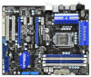
Contents ASRock P55 Extreme4 Motherboard (ATX Form Factor: 12.0-in x 9.6-in, 30.5 cm x 24.4 cm) ASRock P55 Extreme4 Quick Installation Guide ASRock P55 Extreme4 Support CD 1 x 80-conductor Ultra ATA 66/100/133 IDE Ribbon Cable 1 x Ribbon Cable for a 3.5-in Floppy Drive 4 x Serial ATA (SATA) Data - ASRock P55 Extreme4 | User Manual - Page 6
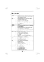
and Pentium® G6950 Processors in LGA1156 Package - Advanced V8 + 2 Power Phase Design - Supports Intel® Turbo Boost Technology - Supports Hyper-Threading Technology (see CAUTION 1) - Supports Untied Overclocking Technology (see CAUTION 2) - Supports EM64T CPU - Intel® P55 - Dual Channel DDR3 Memory - ASRock P55 Extreme4 | User Manual - Page 7
1.0/2.0/3.0 up to 5Gb/s - 6 x SATAII 3.0Gb/s connectors, support RAID (RAID 0, RAID 1, RAID 10, RAID 5 and Intel Rapid Storage), NCQ, AHCI and "Hot Plug" functions - 4 x SATA3 6.0Gb/s connectors - 1 x ATA133 IDE connector (supports 2 x IDE devices) - 1 x Floppy connector - 1 x IR header - 1 x COM - ASRock P55 Extreme4 | User Manual - Page 8
, CPU PLL Voltage Multi-adjustment - Supports I. O. T. (Intelligent Overclocking Technology) Support CD - Drivers, Utilities, AntiVirus Software (Trial Version), ASRock Software Suite (CyberLink DVD Suite - OEM and Trial; THX TruStudio ProTM - OEM) Unique Feature - ASRock OC Tuner (see CAUTION - ASRock P55 Extreme4 | User Manual - Page 9
57. 2. This motherboard supports Untied Overclocking Technology. Please read "Untied Overclocking Technology" on page 48 for details. 3. This motherboard supports Dual Channel Memory Technology. Before you implement Dual Channel Memory Technology, make sure to read the installation guide of memory - ASRock P55 Extreme4 | User Manual - Page 10
mode (S1), Suspend to RAM (S3), hibernation mode (S4) or power off (S5). With APP Charger driver installed, you can easily enjoy the marvelous charging experience than ever. ASRock website: http://www.asrock.com/Feature/AppCharger/index.asp 13. Although this motherboard offers stepless control, it - ASRock P55 Extreme4 | User Manual - Page 11
GeForce GTX295 Driver 195.62 195.62 195.62 195.62 195.62 195.62 195.62 195.62 195.62 195.62 195.62 195.62 * For the latest updates of the supported PCI Express VGA card list for SLITM Mode, please visit our website for details. ASRock website: http://www.asrock.com/support/index - ASRock P55 Extreme4 | User Manual - Page 12
48 PCIE1 P55 Extreme4 LAN PHY 47 PCI Express 2.0 PCIE2 8 CHA_FAN2 SATA3_4 SATA3_3 CHA_FAN3 SATA3_2 SATA3_1 IDE1 9 10 11 12 13 14 15 46 45 44 43 42 41 PCIE3 RoHS Super I/O CMOS Battery ErP/EuP Ready PCIE4 SATA3 6Gb/s NEC USB 3.0 CLRCMOS1 1 Front USB 3.0 PCIE5 Intel P55 RSTBTN AUDIO - ASRock P55 Extreme4 | User Manual - Page 13
1.6 I/O Panel 1 2 3 4 5 8 6 9 7 10 17 16 15 14 1 PS/2 Mouse Port (Green) 2 Coaxial SPDIF Out Port 3 USB 2.0 Port (USB67) * 4 LAN RJ-45 Port 5 Side Speaker (Gray) 6 Rear Speaker (Black) 7 Central / Bass (Orange) 8 Line In (Light Blue) ** 9 Front Speaker (Lime) 13 12 11 10 Microphone - ASRock P55 Extreme4 | User Manual - Page 14
the screws! Doing so may damage the motherboard. 2.2 Pre-installation Precautions Take note of the following precautions before you install motherboard components or change any motherboard settings. 1. Unplug the power cord from the wall socket before touching any component. 2. To avoid damaging - ASRock P55 Extreme4 | User Manual - Page 15
For the installation of Intel 1156-Pin CPU, please follow the steps below. Load Plate Load Lever Contact Array Socket Body 1156-Pin Socket Overview Before you insert the 1156-Pin CPU into the socket, please check if the CPU surface is unclean or if there is any bent pin on the socket. Do not - ASRock P55 Extreme4 | User Manual - Page 16
Heat Sink) up. Locate Pin1 and the two orientation key notches. orientation key notch alignment key Pin1 Pin1 orientation key notch 1156-Pin CPU alignment key 1156-Pin Socket For proper inserting, please ensure to match the two orientation key notches of the CPU with the two alignment keys of - ASRock P55 Extreme4 | User Manual - Page 17
of CPU Fan and Heatsink This motherboard is equipped with 1156-Pin socket that supports Intel 1156-Pin CPU. Please adopt the type of heatsink and cooling fan compliant with Intel 1156-Pin CPU to dissipate heat. Before you installed the heatsink, you need to spray thermal interface material - ASRock P55 Extreme4 | User Manual - Page 18
of Memory Modules (DIMM) This motherboard provides four 240-pin DDR3 (Double Data Rate 3) DIMM slots, and supports Dual Channel Memory Technology. For dual channel configuration, you always need to install identical (the same brand, speed, size and chiptype) DDR3 DIMM pair in the slots of - ASRock P55 Extreme4 | User Manual - Page 19
Installing a DIMM Please make sure to disconnect power supply before adding or removing notch break The DIMM only fits in one correct orientation. It will cause permanent damage to the motherboard and the DIMM if you force the DIMM into the slot at incorrect orientation. Step 3. Firmly insert - ASRock P55 Extreme4 | User Manual - Page 20
or used to install PCI Express graphics cards to support CrossFireXTM or SLITM function. 1. In single VGA card mode, it is recommended to install a PCI Express card before you start the installation. Step 2. Remove the system unit cover (if your motherboard is already installed in a chassis). Step - ASRock P55 Extreme4 | User Manual - Page 21
Guide This motherboard supports NVIDIA® SLITM and Quad SLITM (Scalable Link Interface) technology that allows you to install up to two identical PCI Express x16 graphics cards. Currently, NVIDIA® SLITM technology supports card driver supports NVIDIA® SLITM technology. Download the driver from - ASRock P55 Extreme4 | User Manual - Page 22
Step3. Align and insert ASRock SLI_Bridge_2S Card to the goldfingers on each graphics card. Make sure ASRock SLI_Bridge_2S Card is firmly in place. ASRock SLI_Bridge_2S Card Step4. Connect a VGA cable or a DVI cable to the monitor connector or the DVI connector of the graphics card that is inserted - ASRock P55 Extreme4 | User Manual - Page 23
2.7.2 Driver Installation and Setup Install the graphics card drivers to your system. After that, you can enable the MultiGraphics Processing Unit (GPU) feature in the NVIDIA® nView system tray utility. Please follow the below - ASRock P55 Extreme4 | User Manual - Page 24
For Windows® 7 / 7 64-bit / VistaTM / VistaTM 64-bit OS: (For SLITM and Quad SLITM mode) A. Click the Start icon on your Windows taskbar. B. From the pop-up menu, select All Programs, and then click NVIDIA Corporation. C. Select NVIDIA Control Panel tab. D. Select Control Panel tab. E. From the pop- - ASRock P55 Extreme4 | User Manual - Page 25
Guide This motherboard supports supported with Windows® XP with Service Pack 2 / VistaTM / 7 OS. Quad CrossFireXTM feature are supported with Windows® VistaTM / 7 OS only. Please check AMD website for ATITM CrossFireXTM driver updates graphics card manuals for detailed installation guide. Step 1. - ASRock P55 Extreme4 | User Manual - Page 26
Step 2. Connect two Radeon graphics cards by installing CrossFire Bridge on CrossFire Bridge Interconnects on the top of Radeon graphics cards. (CrossFire Bridge is provided with the graphics card you purchase, not bundled with this motherboard. Please refer to your graphics card vendor for details - ASRock P55 Extreme4 | User Manual - Page 27
Please check AMD website for ATITM driver updates. Step 3. Step 4. Step 5. Install the required drivers to your system. For Windows® XP OS: A. ATITM recommends Windows® XP Service Pack 2 or higher to be installed (If you have Windows® XP Service Pack 2 or higher installed in your system, there is - ASRock P55 Extreme4 | User Manual - Page 28
please check AMD website for updates and details. 2.9 Surround Display Feature This motherboard supports Surround Display upgrade. With the external add-on PCI Express VGA cards, you can easily enjoy the benefits of Surround Display feature. For the detailed instruction, please refer to the document - ASRock P55 Extreme4 | User Manual - Page 29
you select +5V_DUAL, USB devices can wake up the system under S3 (Suspend to RAM) state. USB_PWR3 (see p.12, No. 31) 1_2 +5V 2_3 +5VSB Short pin2 not clear the CMOS right after you update the BIOS. If you need to clear the CMOS when you just finish updating the BIOS, you must boot up the system - ASRock P55 Extreme4 | User Manual - Page 30
the motherboard connect the black end to the IDE devices 80-conductor ATA 66/100/133 cable Note: Please refer to the instruction of SATA3_2 SATA3_1 These four Serial ATA3 (SATA3) connectors support SATA data cables for internal storage devices. The current SATA3 interface allows up to 6.0 Gb/s data - ASRock P55 Extreme4 | User Manual - Page 31
13 P+13 GND DUMMY 1 GND P+12 P-12 USB_PWR Either end of the SATA data cable can be connected to the SATA / SATAII / SATA3 hard disk or the SATAII / SATA3 connector on this motherboard. Please connect the black end of SATA power cable to the power connector on each drive. Then connect the white end - ASRock P55 Extreme4 | User Manual - Page 32
Jack Sensing, but the panel wire on the chassis must support HDA to function correctly. Please follow the instruction in our manual and chassis manual to install your system. 2. If you use AC'97 audio panel, please install it to the front panel audio header as below: A. Connect Mic_IN (MIC) to - ASRock P55 Extreme4 | User Manual - Page 33
PWRBTN (Power Switch): Connect to the power switch on the chassis front panel. You may configure the way to turn off your system using the power switch. RESET (Reset Switch): Connect to the reset switch on the chassis front panel. Press the reset switch to restart the computer if the computer - ASRock P55 Extreme4 | User Manual - Page 34
fan (Quiet Fan) support, the 3-Pin CPU fan still can work successfully even without the fan speed control function. If you plan to connect the 3-Pin CPU fan to the CPU fan connector on this motherboard, please connect it to Pin 1-3. Pin 1-3 Connected 3-Pin Fan Installation ATX Power Connector (24 - ASRock P55 Extreme4 | User Manual - Page 35
of HDMI VGA card to this header. This front USB 3.0 panel can support 2 additional USB 3.0 ports besides the I/O panel. Please connect the to the chassis with the bundled six screws. 2.12 Smart Switches This motherboard has three smart switches: power switch, reset switch and clear CMOS switch, - ASRock P55 Extreme4 | User Manual - Page 36
code information, which makes troubleshooting even easier. Please see the diagrams below for reading the Dr. Debug codes. The Bootblock initialization code Set stack. Bootblock code is copied from ROM to lower system memory and control is given to it. BIOS now executes out of RAM. Both key sequence - ASRock P55 Extreme4 | User Manual - Page 37
initialize any platform specific BIOS modules. Initialize System Management Interrupt. Initializes different devices through DIM. See DIM Code Checkpoints section of document for more information. Initializes different devices. Detects and initializes the video adapter installed in the system that - ASRock P55 Extreme4 | User Manual - Page 38
RAM size if needed. 52 Updates CMOS memory size from memory found in memory test. Allocates memory for Extended BIOS supported) 8E Program the peripheral parameters. Enable/Disable NMI as selected 90 Late POST initialization of system management interrupt. A0 Check boot password if installed - ASRock P55 Extreme4 | User Manual - Page 39
motherboard adopts Intel® P55 chipset that supports Serial ATA (SATA) / Serial ATAII (SATAII) hard disks and RAID (RAID 0, RAID 1, RAID 10, RAID 5, and Intel Rapid Storage) functions. You may install SATA / SATAII hard disks on this motherboard for internal storage devices. This section will guide - ASRock P55 Extreme4 | User Manual - Page 40
Hot Swap Functions for SATA / SATAII HDDs This motherboard supports Hot Plug and Hot Swap functions for SATA / SATAII in RAID / AHCI mode. Intel® P55 chipset provides hardware support for Advanced Host controller Interface (AHCI), a new programming interface for SATA host controllers developed thru - ASRock P55 Extreme4 | User Manual - Page 41
sure the SATA / SATAII / SATA3 driver is installed into system properly. The latest SATA / SATAII / SATA3 driver is available on our support website: www.asrock.com 4. Make sure to use the SATA power cable & data cable, which are from our motherboard package. 5. Please follow below instructions step - ASRock P55 Extreme4 | User Manual - Page 42
below instruction sequence to process the Hot Plug, improper procedure will cause the SATA / SATAII / SATA3 HDD damage and data loss. Step 1 Please connect SATA power cable 1x4-pin end Step 2 Connect SATA data cable to (White) to the power supply 1x4-pin cable. the motherboard's SATAII / SATA3 - ASRock P55 Extreme4 | User Manual - Page 43
If you want to install Windows® XP / XP 64-bit on your SATA / SATAII HDDs with RAID functions, please follow below steps. STEP 1: Set up BIOS. A. Enter BIOS SETUP UTILITY Advanced screen B. Set the option "SATAII Operation Mode" to [RAID]. STEP 2: Make a SATA / SATAII Driver Diskette. Storage - ASRock P55 Extreme4 | User Manual - Page 44
Support CD, "Guide to SATA Hard Disks Installation and RAID Configuration", which is located in the folder at the following path: .. \ RAID Installation Guide STEP 4: Install Windows® XP / XP 64-bit OS on your system. After making a SATA / SATAII driver diskette and using "RAID Installation Guide - ASRock P55 Extreme4 | User Manual - Page 45
the Windows® installation and install all necessary drivers. 6. Install the Intel(R) Rapid Storage software via the CD-ROM included with your motherboard or after downloading it from the Internet. This will add the Intel(R) Rapid Storage Console which can be used to manage the RAID configuration - ASRock P55 Extreme4 | User Manual - Page 46
the instruction to install Windows® 7 / 7 64-bit / VistaTM / VistaTM 64-bit OS on your system. When you see "Where do you want to install Windows?" page, please insert the ASRock Support CD into your optical drive, and click the "Load Driver" button on the left on the bottom to load the Intel® RAID - ASRock P55 Extreme4 | User Manual - Page 47
the SATA / SATAII driver diskette containing the Intel® AHCI driver. After reading the floppy disk, the driver will be presented. Select the driver to install according to the mode you choose and the OS you install. Using SATA / SATAII HDDs without NCQ function STEP 1: Set up BIOS. A. Enter BIOS - ASRock P55 Extreme4 | User Manual - Page 48
1: Set up BIOS. A. Enter BIOS SETUP UTILITY Advanced screen Storage Configuration. B. Set the option "SATAII Operation Mode" to [IDE]. STEP 2: Install Windows® 7 / 7 64-bit / VistaTM / VistaTM 64-bit OS on your system. 2.22 Untied Overclocking Technology This motherboard supports Untied Overclocking - ASRock P55 Extreme4 | User Manual - Page 49
BIOS SETUP UTILITY to configure your system. The BIOS FWH chip on the motherboard stores the BIOS SETUP UTILITY. You may run the BIOS Because the BIOS software is constantly being updated, the following BIOS setup screens set up overclocking features Advanced To set up the advanced BIOS features H/W - ASRock P55 Extreme4 | User Manual - Page 50
Overview System Time System Date [14:00:09] [Fri 06/25/2010] BIOS Version : P55 Extreme4 P1.00 Processor Type : Intel (R) Core (TM) i7 CPU 880 @ 3.07GHz (64bit) Processor Speed : 3066MHz Microcode Update : 106E5/3 Cache Size : 8192KB Total Memory DDR3_A2 DDR3_A1 DDR3_B2 DDR3_B1 : 2048MB - ASRock P55 Extreme4 | User Manual - Page 51
supports this function. Load CPU EZ OC Setting You can use this option to load CPU EZ overclocking setting. Please note that overclocing may cause damage to your CPU and motherboard , please set this item to [Enabled]. Besides the BIOS option, you can also choose our Intelligent Energy Saver utility - ASRock P55 Extreme4 | User Manual - Page 52
you select [Manual], Untied Overclocking function is enabled. Please refer to page 48 for the details of Untied Overclocking Technology. Therefore this item appear to allow you changing the ratio value of this motherboard. QPI Frequency Use this option to adjust QPI (QuickPath Interconnect) frequency - ASRock P55 Extreme4 | User Manual - Page 53
DRAM tFAW DRAM CHA RTL DRAM CHB RTL DRAM tWL DRAM RttNom DRAM RttWr DRAM PD Exit Mode DRAM B2B CAS Delay DRAM Command Rate BIOS SETUP UTILITY 9 [Auto] 9 [Auto] 9 [Auto] 24 [Auto] 74 [Auto] 10 [Auto] 5 [Auto] 4 [Auto] 5 [Auto] 20 [Auto] 52 [Auto] 0 [Auto] 7 [Auto] 60 [Auto] Disabled [Auto] Slow - ASRock P55 Extreme4 | User Manual - Page 54
VDroop Control Use this to enable or disable ASRock VDroop control. Configuration options: [With VDroop] and [Without VDroop]. The default value is [With VDroop]. CPU Voltage Use this to select CPU Voltage. Configuration options: [Auto], [Manual] and [Overdrive Offset]. The default value is [Auto - ASRock P55 Extreme4 | User Manual - Page 55
VTT Voltage Use this to select VTT Voltage. The default value is [Auto]. PCH Voltage Use this to select PCH Voltage. The default value is [Auto]. CPU PLL Voltage Use this to select CPU PLL Voltage. The default value is [Auto]. Would you like to save current setting user defaults? In this option, you - ASRock P55 Extreme4 | User Manual - Page 56
Setting wrong values in this section may cause the system to malfunction. ASRock Instant Flash ASRock Instant Flash is a BIOS flash utility embedded in Flash ROM. This convenient BIOS update tool allows you to update system BIOS without entering operating systems first like MS-DOS or Windows®. Just - ASRock P55 Extreme4 | User Manual - Page 57
motherboard. Enhance Halt State (C1E) All processors support the Halt State (C1). The C1 state is supported through the native processor instructions HLT and MWAIT and requires no hardware support will be hidden if the installed CPU does not support Intel (R) Virtualization Technology. CPU Thermal - ASRock P55 Extreme4 | User Manual - Page 58
Schemes" as "Portable/Laptop" to enable this function. If you install Windows® VistaTM / 7 and want to enable this function, please set this item to [Enabled]. This item will be hidden if the current CPU does not support Intel (R) SpeedStep(tm) tech.. Please note that enabling this function may - ASRock P55 Extreme4 | User Manual - Page 59
3.4.2Chipset Configuration BIOS SETUP UTILITY Advanced Chipset Settings Primary Graphics Adapter Onboard HD Audio Front Panel OnBoard Lan Dr. LAN Link speed : 100Mbps [PCI] [Auto] [Auto] [Enabled] Intel VT-d Configuration +F1 F9 F10 ESC Select Screen Select Item Change Option General Help - ASRock P55 Extreme4 | User Manual - Page 60
ACPI Configuration BIOS SETUP UTILITY Advanced ACPI Configuration Suspend To RAM Check Ready toRAM feature. Select [Auto] will enable this feature if the OS supports it Check Ready Bit Use this item to enable or disable the feature use this motherboard to submit Windows® VistaTM certification. 60 - ASRock P55 Extreme4 | User Manual - Page 61
Plug" and "Link Power Management" will appear. AHCI (Advanced Host Controller Interface) supports NCQ and other new features that will improve SATA disk performance but IDE mode does not have these advantages. SATA3_1 and SATA3_2 RAID Mode Setup SATA3_1, 2 Operation Mode Use this to select SATA3_1 - ASRock P55 Extreme4 | User Manual - Page 62
as the example in the following instruction. BIOS SETUP UTILITY Advanced Primary IDE Master Device :ST340014A :40.0 GB :Supported :16Sectors :4 :MultiWord DMA-2 :Ultra DMA-5 :Supported [Auto] [Auto] [ : [Not Installed], [Auto], [CD/DVD], and [ARMD]. [Not Installed]: Select [Not Installed] to disable - ASRock P55 Extreme4 | User Manual - Page 63
to maximize the IDE hard disk data transfer rate. 3.4.5PCIPnP Configuration BIOS SETUP UTILITY Advanced Advanced PCI / PnP Settings PCI Latency Timer PCI . It is recommended to keep the default value unless the installed PCI expansion cards' specifications require other settings. PCI IDE BusMaster - ASRock P55 Extreme4 | User Manual - Page 64
SETUP UTILITY Advanced Configure Super IO Chipset OnBoard Floppy Controller Serial Port Address Infrared Port Address [Enabled] [3F8 / IRQ4] [Disabled] Allow BIOS to Enable or Disable Floppy Controller. +F1 F9 F10 ESC Select Screen Select Item Change Option General Help Load Defaults Save and - ASRock P55 Extreme4 | User Manual - Page 65
Use this item to enable or disable the use of USB controller. Legacy USB Support Use this option to select legacy support for USB devices. There are four configuration options: [Enabled], [Auto], [Disabled] and [BIOS Setup Only]. The default value is [Enabled]. Please refer to below descriptions for - ASRock P55 Extreme4 | User Manual - Page 66
the CPU temperature, motherboard temperature, CPU fan speed, chassis fan speed, and the critical voltage. BIOS SETUP UTILITY Main OC allows you to set the chassis fan 1 speed. Configuration options: [Full On] and [Manual Mode]. The default is value [Full On]. Chassis Fan 2 Setting This allows you to - ASRock P55 Extreme4 | User Manual - Page 67
F1 General Help F9 Load Defaults F10 Save and Exit ESC Exit v02.54 (C) Copyright 1985-2005, American Megatrends, Inc. 3.6.1 Boot Settings Configuration BIOS SETUP UTILITY Boot Boot Settings Configuration Full Screen Logo AddOn ROM Display Boot Logo Boot From Onboard LAN Bootup Num-Lock [Enabled - ASRock P55 Extreme4 | User Manual - Page 68
: [Auto], [EuP], [Scenery] and [ASRock]. The default value is [Auto]. Boot From BIOS SETUP UTILITY Main OC Tweaker Advanced H/W Monitor Boot Security Exit Security Settings Supervisor Password : Not Installed User Password : Not Installed Change Supervisor Password Change User Password Install - ASRock P55 Extreme4 | User Manual - Page 69
Security Exit Exit Options Save Changes and Exit Discard Changes and Exit Discard Changes Load BIOS Defaults Load Performance Setup Default (IDE/SATA) Load Performance Setup AHCI Mode Load Performance Setup RAID Mode Load Power Saving Setup Default Exit system setup after saving the changes. F10 - ASRock P55 Extreme4 | User Manual - Page 70
Please install the necessary drivers to activate the devices. 4.2.3 Utilities Menu The Utilities Menu shows the applications software that the motherboard supports. Click on a specific item then follow the installation wizard to install it. 4.2.4 Contact Information If you need to contact ASRock or
-
 1
1 -
 2
2 -
 3
3 -
 4
4 -
 5
5 -
 6
6 -
 7
7 -
8
-
9
-
10
-
11
-
12
-
13
-
14
-
15
-
16
-
17
-
18
-
19
-
20
-
21
-
22
-
23
-
24
-
25
-
26
-
27
-
28
-
29
-
30
-
31
-
32
-
33
-
34
-
35
-
36
-
37
-
38
-
39
-
40
-
41
-
42
-
43
-
44
-
45
-
46
-
47
-
48
-
49
-
50
-
51
-
52
-
53
-
54
-
55
-
56
-
57
-
58
-
59
-
60
-
61
-
62
-
63
-
64
-
65
-
66
-
67
-
68
-
69
-
70
 |
 |

1
P55 Extreme4
User Manual
Version 1.0
Published June 2010
Copyright©2010 ASRock INC. All rights reserved.