ASRock P55 Extreme4 User Manual - Page 12
Dual Channel: DDR3_A2, DDR3_B2, Blue - p55
 |
View all ASRock P55 Extreme4 manuals
Add to My Manuals
Save this manual to your list of manuals |
Page 12 highlights
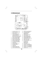
1.5 Motherboard Layout 1 23 4 5 6 7 24.4cm (9.6 in) PS2 Mouse PS2 Keyboard Clr CMOS 1 PS2_USB_PWR1 PWR_FAN1 ATX12V1 Designed in Taipei Dual Channel DDR3 2600+ CPU_FAN1 DDR3_A2 (64 bit, 240-pin module) DDR3_A1 (64 bit, 240-pin module) DDR3_B2 (64 bit, 240-pin module) DDR3_B1 (64 bit, 240-pin module) ATXPWR1 30.5cm (12.0 in) Coaxial SPDIF Optical SPDIF eSATA3 49 USB 2.0 T: USB6 B: USB7 USB 2.0 T: USB0 B: USB1 USB 3.0 T: USB0 B: USB1 1 USB_PWR2 USB 2.0 T: USB4 Top: B: USB5 RJ-45 Top: SIDE SPK Center: REAR SPK FRONT Bottom: CTR BASS MIC IN Top: LINE IN Center: Bottom: 48 PCIE1 P55 Extreme4 LAN PHY 47 PCI Express 2.0 PCIE2 8 CHA_FAN2 SATA3_4 SATA3_3 CHA_FAN3 SATA3_2 SATA3_1 IDE1 9 10 11 12 13 14 15 46 45 44 43 42 41 PCIE3 RoHS Super I/O CMOS Battery ErP/EuP Ready PCIE4 SATA3 6Gb/s NEC USB 3.0 CLRCMOS1 1 Front USB 3.0 PCIE5 Intel P55 RSTBTN AUDIO CODEC 1 IR1 HD_AUDIO1 HDMI_SPDIF1 1 CD1 1 1 COM1 PCI1 PCI2 FLOPPY1 USB3_2_3 PWRBTN USB12_13 SATAII_5 SATAII_6 16Mb BIOS Dr. SATAII_3 SATAII_4 Debug SATAII_1 SATAII_2 1 USB10_11 1 USB8_9 1 USB_PWR3 SPEAKER1 PLED1 1 1 1 PLED PWRBTN 1 HDLED RESET PANEL1 CHA_FAN1 16 17 18 19 20 21 22 23 24 40 39 38 37 36 35 34 33 32 31 30 29 28 27 26 25 1 ATX 12V Power Connector (ATX12V1) 2 PS2_USB_PWR1 Jumper 3 Power Fan Connector (PWR_FAN1) 4 1156-Pin CPU Socket 5 CPU Fan Connector (CPU_FAN1) 6 2 x 240-pin DDR3 DIMM Slots (Dual Channel: DDR3_A2, DDR3_B2, Blue) 7 2 x 240-pin DDR3 DIMM Slots (Dual Channel: DDR3_A1, DDR3_B1, White) 8 Chassis Fan Connector (CHA_FAN2) 9 ATX Power Connector (ATXPWR1) 10 SATA3 Connector (SATA3_4, White) 11 SATA3 Connector (SATA3_3, White) 12 Chassis Fan Connector (CHA_FAN3) 13 SATA3 Connector (SATA3_2, White) 14 SATA3 Connector (SATA3_1, White) 15 Clear CMOS Jumper (CLRCMOS1) 16 Primary IDE Connector (IDE1, Blue) 17 Intel P55 Chipset 18 Reset Switch (RSTBTN) 19 SATAII Connector (SATAII_3, Blue ) 20 Power Switch (PWRBTN) 21 16Mb SPI Flash 22 Dr. Debug (LED) 23 SATAII Connector (SATAII_1, Blue ) 24 SATAII Connector (SATAII_2, Blue ) 25 Chassis Fan Connector (CHA_FAN1) 26 System Panel Header (PANEL1, White) 27 SATAII Connector (SATAII_4, Blue ) 28 Power LED Header (PLED1) 29 Chassis Speaker Header (SPEAKER 1, White) 30 SATAII Connector (SATAII_6, Blue ) 31 USB_PWR3 Jumper 32 USB 2.0 Header (USB8_9, Blue) 33 SATAII Connector (SATAII_5, Blue ) 34 USB 2.0 Header (USB10_11, Blue) 35 USB 2.0 Header (USB12_13, Blue) 36 USB 3.0 Header (USB3_2_3, Light Blue) 37 Floppy Connector (FLOPPY1) 38 COM Port Header (COM1) 39 Internal Audio Connector: CD1 (White) 40 Front Panel Audio Header (HD_AUDIO1, White) 41 HDMI_SPDIF Header (HDMI_SPDIF1, White) 42 PCI Slots (PCI1-2) 43 Infrared Module Header (IR1) 44 PCI Express 2.0 x16 Slot (PCIE5, Blue) 45 PCI Express 2.0 x1 Slot (PCIE4, White) 46 PCI Express 2.0 x1 Slot (PCIE3, White) 47 PCI Express 2.0 x16 Slot (PCIE2, Blue) 48 PCI Express 2.0 x1 Slot (PCIE1, White) 49 USB_PWR2 Jumper 12
-
 1
1 -
2
-
3
-
4
-
5
-
6
-
 7
7 -
 8
8 -
 9
9 -
 10
10 -
 11
11 -
 12
12 -
 13
13 -
 14
14 -
 15
15 -
 16
16 -
 17
17 -
18
-
19
-
20
-
21
-
22
-
23
-
24
-
25
-
26
-
27
-
28
-
29
-
30
-
31
-
32
-
33
-
34
-
35
-
36
-
37
-
38
-
39
-
40
-
41
-
42
-
43
-
44
-
45
-
46
-
47
-
48
-
49
-
50
-
51
-
52
-
53
-
54
-
55
-
56
-
57
-
58
-
59
-
60
-
61
-
62
-
63
-
64
-
65
-
66
-
67
-
68
-
69
-
70
 |
 |
