ASRock QC5000M Quick Installation Guide
ASRock QC5000M Manual
 |
View all ASRock QC5000M manuals
Add to My Manuals
Save this manual to your list of manuals |
ASRock QC5000M manual content summary:
- ASRock QC5000M | Quick Installation Guide - Page 1
change without notice, and should not be constructed as a commitment by ASRock. ASRock assumes no responsibility for any errors or omissions that may appear in CALIFORNIA, USA ONLY he Lithium battery adopted on this motherboard contains Perchlorate, a toxic substance controlled in Perchlorate Best - ASRock QC5000M | Quick Installation Guide - Page 2
he terms HDMI™ and HDMI High-Deinition Multimedia Interface, and the HDMI logo are trademarks or registered trademarks of HDMI Licensing LLC in the United States and other countries. - ASRock QC5000M | Quick Installation Guide - Page 3
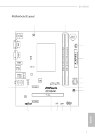
COM1 Motherboard Layout 1 USB 2.0 T: USB0 B: USB1 CPU_FAN1 QC5000M 2 CMOS Battery CHA_FAN1 3 DDR3_A1 (64 bit, 240-FpinSBmo8d0ul0e) DDR3_A2 (64 bit, 240-pin module) ATXPWR1 VGA1 RoHS 4 HDMI1 USB 3.0 T: USB0 B: USB1 USB 3.0 RJ-45 LAN USB 2.0 T: USB2 B: USB3 LAN HD_AUDIO1 1 32Mb BIOS Top - ASRock QC5000M | Quick Installation Guide - Page 4
No. Description 1 CPU Fan Connector (CPU_FAN1) 2 2 x 240-pin DDR3 DIMM Slots (DDR3_A1, DDR3_A2) 3 Chassis Fan Connector (CHA_FAN1) 4 ATX Power Connector (ATXPWR1) 5 SATA3 Connector (SATA3_1) 6 SATA3 Connector (SATA3_2) 7 USB 2.0 Header (USB4_5) 8 Chassis Fan Connector (CHA_FAN2) 9 - ASRock QC5000M | Quick Installation Guide - Page 5
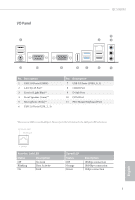
I/O Panel 1 QC5000M 3 2 4 11 10 No. Description 1 USB 2.0 Ports (USB01) 2 LAN RJ-45 Port* 3 Line In (Light Blue)** 4 Front Speaker (Lime)** 5 Microphone (Pink)** 6 USB 2.0 Ports (USB_2_3) 9 8 7 6 5 No. Description 7 - ASRock QC5000M | Quick Installation Guide - Page 6
7.1 CH HD Audio, it is required to use an HD front panel audio module and enable the multichannel audio feature through the audio driver. Please set Speaker Coniguration to "7.1 Speaker"in the Realtek HD Audio Manager. Function of the Audio Ports in 7.1-channel Coniguration: Port Light Blue - ASRock QC5000M | Quick Installation Guide - Page 7
You may ind the latest VGA cards and CPU support list on ASRock's website as well. ASRock website http://www.asrock.com. 1.1 Package Contents • ASRock QC5000M Motherboard (Micro ATX Form Factor) • ASRock QC5000M Quick Installation Guide • ASRock QC5000M Support CD • 2 x Serial ATA (SATA) Data Cables - ASRock QC5000M | Quick Installation Guide - Page 8
• High Density Glass Fabric PCB CPU • AMD FT3 Kabini A4-5000 Quad-Core APU Memory • 2 x DDR3 DIMM Slots • Supports DDR3 1600/1333/1066 non-ECC, un-bufered memory • audio feature through the audio driver. • Supports Surge Protection (ASRock Full Spike Protection) • ELNA Audio Caps English 6 - ASRock QC5000M | Quick Installation Guide - Page 9
QC5000M LAN Rear Panel I/O Storage Connector BIOS Feature • PCIE x1 Gigabit LAN 10/100/1000 Mb/s • Realtek RTL8111GR • Supports Wake-On-WAN • Supports Wake-On-LAN • Supports Lightning/ESD Protection (ASRock Full Spike Protection) • Supports LAN Cable Detection • Supports Energy Eicient Ethernet - ASRock QC5000M | Quick Installation Guide - Page 10
* USB 3.0 is not supported by Windows® XP * For the updated Windows® 10 driver, please visit ASRock's website for details: http://www.asrock.com Certiications • FCC, CE asrock.com Please realize that there is a certain risk involved with overclocking, including adjusting the setting in the BIOS - ASRock QC5000M | Quick Installation Guide - Page 11
QC5000M Chapter 2 Installation his is a Micro ATX form factor motherboard. Before you install the motherboard, study the coniguration of your chassis to ensure that the motherboard its into it. Pre-installation Precautions Take note of the following precautions before you install motherboard - ASRock QC5000M | Quick Installation Guide - Page 12
3) DIMM slots. It is not allowed to install a DDR or DDR2 memory module into a DDR3 slot; otherwise, this motherboard and DIMM may be damaged. he DIMM only its in one correct orientation. It will cause permanent damage to the motherboard and the DIMM if you force the DIMM into the slot at incorrect - ASRock QC5000M | Quick Installation Guide - Page 13
QC5000M 1 2 3 11 English - ASRock QC5000M | Quick Installation Guide - Page 14
2.2 Expansion Slots (PCI Express Slots) here are 3 PCI Express slots on the motherboard. Before installing an expansion card, please make sure that the power supply is switched of or the power cord is unplugged. Please read the documentation - ASRock QC5000M | Quick Installation Guide - Page 15
QC5000M 2.3 Jumpers Setup he illustration shows how jumpers are setup. When the jumper cap is seconds. However, please do not clear the CMOS right ater you update the BIOS. If you need to clear the CMOS when you just inish updating the BIOS, you must boot up the system irst, and then shut it down - ASRock QC5000M | Quick Installation Guide - Page 16
jumper caps over these headers and connectors. Placing jumper caps over the headers and connectors will cause permanent damage to the motherboard. System Panel Header (9-pin PANEL1) (see p.1, No. 9) PLED+ PLEDPWRBTN# GND 1 GND RESET# GND HDLEDHDLED+ Connect the power switch, reset switch and - ASRock QC5000M | Quick Installation Guide - Page 17
SATA3_1 SATA3_2 QC5000M hese two SATA3 connectors support SATA data cables on this motherboard. Each USB 2.0 header can support two ports supports Jack Sensing, but the panel wire on the chassis must support HDA to function correctly. Please follow the instructions in our manual and chassis manual - ASRock QC5000M | Quick Installation Guide - Page 18
and match the black wire to the ground pin. 12 24 1 13 his motherboard provides a 24-pin ATX power connector. To use a 20-pin ATX power supply, please plug it along Pin 1 and Pin 13. his connector supports Trusted Platform Module (TPM) system, which can 1 securely store keys, digital - ASRock QC5000M | Quick Installation Guide - Page 19
Liste unterstützter VGA-Karten und Prozessoren auf der ASRock-Webseite: ASRock-Webseite http://www.asrock.com. 1.1 Lieferumfang • ASRock QC5000M-Motherboard (Mini-ITX-Formfaktor) • ASRock QC5000M-Schnellinstallationsanleitung • ASRock QC5000M-Support-CD • 2 x Serial-ATA- (SATA) Datenkabel (optional - ASRock QC5000M | Quick Installation Guide - Page 20
Glasfasergewebe Prozessor • AMD A4-5000, Quadcore-APU (Kabini, FT3) Speicher • 2 x DDR3-DIMM-Steckplätze • Unterstützt DDR3 1600/1333/1066 non- über den Audiotreiber aktivieren. • Unterstützt Überspannungsschutz (ASRocks Komplettschutz vor Spannungsspitzen) • ELNA-Audiokondensatoren Deutsch 18 - ASRock QC5000M | Quick Installation Guide - Page 21
2.0-Stitleisten (unterstützt vier USB 2.0-Ports) (Unterstützt Schutz vor elektrostatischer Entladung (ASRocks Komplettschutz vor Spannungsspitzen)) • 32-Mb-AMI-UEFI-Legal-BIOS mit Unterstützung mehrsprachiger graischer Benutzerschnittstellen • Unterstützung für "Plug and Play" • ACPI 1.1-konforme - ASRock QC5000M | Quick Installation Guide - Page 22
wird von Windows® XP nicht unterstützt * Weitere Informationen zum aktualisierten Windows® 10-Treiber inden Sie auf der ASRock-Webseite: http://www.asrock.com Zertiizierungen • FCC, CE, WHQL • ErP/EuP ready (ErP/EuP ready-Netzteil erforderlich) * Detaillierte Produktinformationen inden Sie auf - ASRock QC5000M | Quick Installation Guide - Page 23
QC5000M 1.3 Jumper-Einrichtung Die Abbildung zeigt, wie die Jumper eingestellt werden. Jumper-Kappe kurz. Löschen Sie den CMOS jedoch nicht direkt nach der BIOS-Aktualisierung. Falls Sie den CMOS direkt nach Abschluss der BIOS-Aktualisierung löschen müssen, starten Sie das System zunächst; fahren Sie - ASRock QC5000M | Quick Installation Guide - Page 24
Stitleisten und Anschlüssen an. Durch Anbringen von Jumper-Kappen an diesen Stitleisten und Anschlüssen können Sie das Motherboard dauerhat beschädigen. Systemblende-Stitleiste (9-polig, PANEL1) (siehe S. 1, Nr. 9) PLED+ PLEDPWRBTN# GND 1 GND RESET# GND HDLEDHDLED+ Verbinden Sie Netzschalter - ASRock QC5000M | Quick Installation Guide - Page 25
Nr. 5) (SATA3_2: siehe S. 1, Nr. 6) SATA3_1 SATA3_2 QC5000M Diese zwei SATA-IIIAnschlüsse unterstützen SATA-Datenkabel für interne USB 2.0-Ports an der E/A-Blende beinden sich zwei Stitleisten an diesem Motherboard. Jede USB 2.0-Stitleiste kann zwei Ports unterstützen. Audiostitleiste 1 - ASRock QC5000M | Quick Installation Guide - Page 26
den Lüteranschlüssen; der schwarze Draht gehört zum Erdungskontakt. ATX-Netzanschluss (24-polig, ATXPWR1) (siehe S. 1, Nr. 4) 12 24 1 13 Dieses Motherboard bietet einen 24-poligen ATX-Netzanschluss. Bitte schließen Sie es zur Nutzung eines 20-poligen ATX-Netzteils entlang Kontakt 1 und Kontakt - ASRock QC5000M | Quick Installation Guide - Page 27
siehe S. 1, Nr. 13) GND SERIRQ # S_PWRDWN # GN D LAD1 LAD2 SMB_DATA_MAIN SMB_CLK_MAIN GN D +3VS B LAD0 +3V LAD3 PCIRST # FRAM E PCICLK GN D QC5000M Dieser Anschluss unterstützt das Trusted Platform Module- (TPM) 1 System, das Schlüssel, digitale Zertiikate, Kennwörter und Daten sicher aubewahren - ASRock QC5000M | Quick Installation Guide - Page 28
également disponible sur le site Internet de ASRock. Site Internet ASRock http://www.asrock.com. 1.1 Contenu de l'emballage • Carte mère ASRock QC5000M (facteur de forme Mini-ITX) • Guide d'installation rapide ASRock QC5000M • CD d'assistance ASRock QC5000M • 2 x câbles de données Serial ATA (SATA - ASRock QC5000M | Quick Installation Guide - Page 29
QC5000M 1.2 Spéciications Plateforme Processeur Mémoire Fente d'expansion Graphiques Audio • Facteur de forme Micro ATX • Conception à condensateurs solides • PCB High Density Glass Fabric • APU AMD Quad Core FT3 Kabini A4-5000 • 2 x fentes DIMM DDR3 • Prend en charge les mémoires sans tampon non - ASRock QC5000M | Quick Installation Guide - Page 30
x connecteur audio panneau frontal • 2 x embases USB 2.0 (pour 4 ports USB 2.0) (Supporte la protection ESD (protection complète contre surges ASRock)) • BIOS UEFI AMI 32Mo avec prise en charge d'interface graphique multilingue • Support du "Plug and Play" • Compatible ACPI 1.1 Wake Up Events Fran - ASRock QC5000M | Quick Installation Guide - Page 31
QC5000M • Prend en charge SMBIOS 2.3.1 • Réglage de la tension DRAM XP 64-bit * USB 3.0 n'est pas supporté par Windows® XP * Pour obtenir le pilote Windows® 10 mis à jour, veuillez vous rendre sur le site Web d'ASRock pour plus de détails : http://www.asrock.com Certiications • FCC, CE, WHQL • - ASRock QC5000M | Quick Installation Guide - Page 32
la broche 3 sur CLRCMOS1 pendant 5 secondes. Toutefois, n'efacez pas la CMOS immédiatement après avoir mis à jour le BIOS. Si vous avez besoin d'efacer les données CMOS après une mise à jour du BIOS, vous devez tout d'abord redémarrer le système, puis l'éteindre avant de procéder à l'efacement de la - ASRock QC5000M | Quick Installation Guide - Page 33
QC5000M 1.4 Embases et connecteurs de la carte mère Les embases et connecteurs situés sur la carte NE SONT PAS des cavaliers. Ne placez JAMAIS de capuchons - ASRock QC5000M | Quick Installation Guide - Page 34
Jack Sensing (détection de la iche), mais le panneau grillagé du châssis doit être compatible avec la HDA pour fonctionner correctement. Veuillez suivre les instructions igurant dans notre manuel et dans le manuel du châssis pour installer votre système. 2. Si vous utilisez un panneau audio AC'97 - ASRock QC5000M | Quick Installation Guide - Page 35
QC5000M Embase du haut-parleur du châssis (SPEAKER1 à 4 broches) (voir p.1, No. 10) DUMMY SPEAKER 1 +5V DUMMY Veuillez brancher le hautparleur du châssis sur cette - ASRock QC5000M | Quick Installation Guide - Page 36
GN D Français Embase TPM (TPMS1 à 17 broches) (voir p.1, No. 13) GND SERIRQ # S_PWRDWN # GN D LAD1 LAD2 SMB_DATA_MAIN SMB_CLK_MAIN GN D +3VS B LAD0 +3V LAD3 PCIRST # FRAM E PCICLK Ce connecteur prend en charge un module TPM (Trusted Platform Module 1 - Module de plateforme sécurisée), qui permet - ASRock QC5000M | Quick Installation Guide - Page 37
supporto di CPU anche sul sito Web di ASRock. Sito Web di ASRock http://www.asrock.com. 1.1 Contenuto della confezione • Scheda madre QC5000M ASRock (fattore di forma Mini-ITX) • Guida rapida di installazione QC5000M ASRock • CD di supporto QC5000M ASRock • 2 x cavi dati Serial ATA (SATA) (opzionali - ASRock QC5000M | Quick Installation Guide - Page 38
in vetro ad alta densità • APU AMD Quad-Core FT3 Kabini A4-5000 • 2 x slot DIMM DDR3 • Supporta la memoria DDR3 1600/1333/1066 non ECC, senza bufer • Capacità funzione audio multicanale tramite il driver audio. • Supporto protezione da sovratensione (protezione completa ASRock dai picchi di corrente) - ASRock QC5000M | Quick Installation Guide - Page 39
QC5000M LAN I/O pannello posteriore Archiviazione Connettore Caratteristiche del BIOS • PCIE x 1 LAN Gigabit 10/100/1000 Mb/s • Realtek RTL8111GR • Supporto WOW (Wake-On-WAN) • Supporta Wake-On-LAN • Supporto la protezione da fulmini/scariche elettrostatiche (ESD) (protezione completa ASRock dai - ASRock QC5000M | Quick Installation Guide - Page 40
32-bit / 7 a 64-bit / XP a 32-bit / XP a 64-bit * Windows® XP non supporta USB 3.0 * Driver aggiornato di Windows® 10, visitare il sito ASRock per i dettagli: http://www.asrock.com • FCC, CE, WHQL • ErP/EuP Ready (è necessaria alimentazione ErP/EuP ready) * Per informazioni dettagliate sul prodotto - ASRock QC5000M | Quick Installation Guide - Page 41
QC5000M 1.3 Impostazione jumper L'illustrazione mostra in che modo vengono impostati i jumper. Tuttavia, non azzerare la CMOS subito dopo aver aggiornato il BIOS. Se è necessario azzerare la CMOS dopo l'aggiornamento del BIOS, è necessario riavviare prima il sistema e in seguito spegnerlo prima - ASRock QC5000M | Quick Installation Guide - Page 42
1.4 Header e connettori sulla scheda Gli header e i connettori sulla scheda NON sono jumper. NON posizionare cappucci del jumper su questi header e connettori. Il posizionamento di cappucci del jumper su header e connettori provocherà danni permanenti alla scheda madre. Header sul pannello del - ASRock QC5000M | Quick Installation Guide - Page 43
pag.1, n. 5) (SATA3_2: vedere pag. 1, n. 6) SATA3_1 SATA3_2 QC5000M Questi due connettori SATA3 supportano cavi dati SATA per dispositivi di archiviazione funzionare correttamente. Seguire le istruzioni presenti nel nostro manuale e nel manuale dello chassis per installare il sistema. 2. Se si - ASRock QC5000M | Quick Installation Guide - Page 44
Header altoparlante chassis (SPEAKER1 a 4 pin) (vedere pag. 1, n. 10) Connettori della ventola della chassis (CHA_FAN1 a 4 pin) (vedere pag. 1, n. 3) (CHA_FAN2 a 3 pin) (vedere pag. 1, n. 8) Connettori della ventola della CPU (CPU_FAN1 a 3 pin) (vedere pag. 1, n. 1) DUMMY SPEAKER 1 +5V DUMMY - ASRock QC5000M | Quick Installation Guide - Page 45
de la CPU, en el sitio web de ASRock. Sitio web de ASRock http://www.asrock.com. 1.1 Contenido del paquete • Placa base ASRock QC5000M (Factor de forma Mini-ITX) • Guía de instalación rápida de ASRock QC5000M • CD de soporte de ASRock QC5000M • 2 cables de datos Serie ATA (SATA) (Opcional - ASRock QC5000M | Quick Installation Guide - Page 46
PCB de ibra de vidrio de alta densidad • APU AMD FT3 Kabini A4-5000 Quad-Core • 2 ranuras DDR3 DIMM • Compatible con memoria no-ECC, sin búfer DDR3 1600/1333/1066 • Capacidad máxima de la memoria del subidas de tensión (Protección Integral contra Picos de ASRock) • ELNA Audio Caps. Español 44 - ASRock QC5000M | Quick Installation Guide - Page 47
QC5000M LAN Panel trasero I/O Almacenamiento Conectores Características del BIOS • LAN Gigabit PCIE x1 10/100/1000 Mb/s • Realtek RTL8111GR • Admite Reactivación en WAN • Compatible con Wake-On-LAN • Admite protección contra rayos/ESD (Protección Integral contra Picos de ASRock) • Admite detección - ASRock QC5000M | Quick Installation Guide - Page 48
bits * Windows® XP no admite USB 3.0 * Para obtener el controlador actualizado para Windows® 10, visite el sitio Web desde ASRock para obtener detalles: http://www.asrock.com • FCC, CE, WHQL • Compatible con ErP/EuP (requiere toma de alimentación compatible con ErP/EuP) * Para obtener más informaci - ASRock QC5000M | Quick Installation Guide - Page 49
QC5000M 1.3 Instalación de los puentes La instalación muestra cómo deben instalarse embargo, no borre el CMOS justo después de que haya actualizado el BIOS. Si necesita borrar el CMOS cuando acabe de actualizar el BIOS, deberá arrancar el sistema primero y, a continuación, deberá apagarlo antes de - ASRock QC5000M | Quick Installation Guide - Page 50
1.4 Conectores y cabezales incorporados Los cabezales y conectores incorporados NO son puentes. NO coloque tapas de puente sobre estos cabezales y conectores. Si coloca tapas de puente sobre los cabezales y conectores dañará de forma permanente la placa base. Cabezal del panel del sistema (PANEL1 - ASRock QC5000M | Quick Installation Guide - Page 51
QC5000M Conectores Serie ATA3 (SATA3_1: consulte la pág.1, N.º 5) (SATA3_2: consulte la compatible con HDA para que pueda funcionar correctamente. Siga las instrucciones que se indican en nuestro manual y en el manual del chasis para instalar su sistema. 2. Si utiliza un panel de audio AC'97, inst - ASRock QC5000M | Quick Installation Guide - Page 52
Cabezal de altavoces del chasis (SPEAKER1 de 4 pines) (consulte la pág.1, N.º 10) Conectores del ventilador de la chasis (CHA_FAN1 de 4 pines) (consulte la pág.1, N.º 3) (CHA_FAN2 de 3 pines) (consulte la pág.1, N.º 8) Conectores del ventilador de la CPU (CPU_FAN1 de 3 pines) (consulte la pág.1, N.º - ASRock QC5000M | Quick Installation Guide - Page 53
pines) (consulte la pág.1, N.º 13) GND SERIRQ # S_PWRDWN # GN D LAD1 LAD2 SMB_DATA_MAIN SMB_CLK_MAIN GN D +3VS B LAD0 +3V LAD3 PCIRST # FRAM E PCICLK GN D QC5000M Este conector es compatible con el sistema Módulo de Plataforma 1 Segura (TPM, en inglés), que puede almacenar de forma segura claves - ASRock QC5000M | Quick Installation Guide - Page 54
1 ASRock QC5000M ASRock ASRock BIOS ASRock ASRock VGA ASRock http:// www.asrock.com. 1.1 ASRock QC5000M Mini-ITX ASRock QC5000M ASRock QC5000M • 2 Serial ATA (SATA 1 52 - ASRock QC5000M | Quick Installation Guide - Page 55
QC5000M 1.2 Micro ATX High Density Glass Fabric PCB ЦП • 4 AMD FT3 Kabini A4-5000 Память • 2 DDR3 DIMM DDR3 1600/1333/1066 Non- ECC Unbufered 32 Гб • 1 x PCI Express 2.0 x16 PCIE2 x16) • 2 x PCI Express 2.0 x1 AMD RadeonTM HD 8330 • DirectX 11.1, Pixel Shader 5.0 2 - ASRock QC5000M | Quick Installation Guide - Page 56
. • PCIE x1 Gigabit LAN 10/100/1000 Realtek RTL8111GR Wake-On-WAN Wake-On-LAN ASRock Energy Eicient Ethernet 802.3az PXE • 1 x PS/2 1 x порт COM1 • 1 x D-Sub • 1 x HDMI • 4 x USB 2.0 ASRock 2 x USB 3.0 ASRock 1 x RJ-45 ACT/LINK и МИД SPEED HD Audio • 2 x SATA3 6,0 NCQ, AHCI - ASRock QC5000M | Quick Installation Guide - Page 57
QC5000M BIOS • 32 Мб AMI UEFI Legal BIOS Plug and Play ACPI 1.1 SMBIOS 2.3.1 DRAM 12 В, +5 В, +3,3 В, ЦП Vcore ОС • Microsot® Windows® 10 64 8.1 32 / 8.1 64 8 32 8 64 7 32 7 64 XP 32 XP 64 * USB 3.0 Windows® XP Windows® 10 ASRock http://www.asrock.com - ASRock QC5000M | Quick Installation Guide - Page 58
1.3 3 1 и 2 CMOS (CLRCMOS1 1, № 11) CMOS CLRCMOS1 CMOS 15 2 и 3 на CLRCMOS1 на 5 CMOS BIOS CMOS BIOS CMOS CMOS. 56 - ASRock QC5000M | Quick Installation Guide - Page 59
QC5000M 1.4 9 PANEL1 1, № 9) PLED+ PLEDPWRBTN# GND 1 GND RESET# GND HDLEDHDLED+ PWRBTN RESET PLED S3 S4 S5 HDLED 57 - ASRock QC5000M | Quick Installation Guide - Page 60
Serial ATA3 (SATA3_1 1, № 5) (SATA3_2 1, № 6) SATA3_1 SATA3_2 SATA3 SATA 6,0 Гб/с. USB 2.0. (9 USB4_5 1, № 7) (9 USB6_7 1, № 12) USB_PWR PP+ GND DUMMY 1 GND P+ PUSB_PWR USB 2.0 USB 2.0 1 9 HD_ AUDIO1) MIC2_L MIC2_R OUT2_R J_SENS E OUT2_L 1, № 14) GND - ASRock QC5000M | Quick Installation Guide - Page 61
QC5000M 4 SPEAKER1 1, № 10) DUMMY SPEAKER 1 +5V DUMMY 4 CHA_ FAN1 1, № 3) (3 CHA_ FAN2 1, № 8) 3 CPU_FAN1 1, № 1) 24 ATXPWR1 1, № 4) GND +12V CHA_FAN_SPEED FAN_SPEED_CONTROL GND FAN_VOLTAGE CHA_FAN_SPEED GND FAN_VOLTAGE CPU_FAN_SPEED 12 24 1 - ASRock QC5000M | Quick Installation Guide - Page 62
CPU mais recentes suportadas no Web site da ASRock. Web site da ASRock http://www.asrock.com. 1.1 Conteúdo da embalagem • Placa principal ASRock QC5000M (Formato Mini-ITX) • Guia de instalação rápida do ASRock QC5000M • CD de suporte do ASRock QC5000M • 2 x Cabos de dados Serial ATA (SATA) (Opcional - ASRock QC5000M | Quick Installation Guide - Page 63
QC5000M 1.2 Especiicações Plataforma CPU Memória Ranhuras de expansão Gráicos Áudio • Formato Micro ATX • Design de condensador sólido • PCB de Fibra de Vidro de Alta Densidade • APU Quad-Core AMD FT3 Kabini A4-5000 • 2 x ranhuras DIMM DDR3 • Suporta memória DDR3 1600/1333/1066, não ECC, sem memó - ASRock QC5000M | Quick Installation Guide - Page 64
pinos ATX • 1 x conector de áudio do painel frontal • 2 x terminais USB 2.0 (suporte para 4 portas USB 2.0) (Suporta Proteção ESD (Proteção Total contra Picos ASRock)) • BIOS UEFI oicial da AMI com 32Mb com suporte de interface multilíngue • Suporta dispositivos "Plug and Play" • Eventos de reactiva - ASRock QC5000M | Quick Installation Guide - Page 65
QC5000M Monitor de Hardware Sistema Operativo Certiicações • Sensor de USB 3.0 não é suportado pelo Windows® XP * Para o driverWindows® 10 atualizado, visite o website da ASRock para detalhes: http://www.asrock.com • FCC, CE, WHQL • Preparada para ErP/EuP (é necessária uma fonte de alimentação - ASRock QC5000M | Quick Installation Guide - Page 66
e o pino3 no CLRCMOS1 durante 5 segundos. No entanto, não limpe o CMOS logo após ter efectuado a actualização da BIOS. Se precisar de limpar o CMOS logo após ter terminado uma actualização da BIOS, deverá primeiro iniciar o sistema e voltar a encerrá-lo antes de efectuar a acção de limpeza do CMOS - ASRock QC5000M | Quick Installation Guide - Page 67
QC5000M 1.4 Terminais e conectores integrados Os terminais e conectores integrados NÃO são jumpers. NÃO coloque tampas de jumpers sobre estes terminais e conectores. Colocar tampas de jumpers sobre os terminais e conectores irá - ASRock QC5000M | Quick Installation Guide - Page 68
deinição suporta Detecção de icha, mas o cabo de painel no chassis deverá suportar HDA para funcionar correctamente. Siga as instruções no nosso manual e no manual do chassis para instalar o seu sistema. 2. Se utilizar um painel de áudio AC'97, instale-o no terminal de áudio do painel frontal de - ASRock QC5000M | Quick Installation Guide - Page 69
QC5000M Português Terminal do altifalante do chassis (SPEAKER1 de 4 pinos) (consultar p.1, N.º 10) DUMMY SPEAKER 1 +5V DUMMY Ligue o altifalante do chassis a este terminal. Conectores da ventoinha da - ASRock QC5000M | Quick Installation Guide - Page 70
ncel VGA kartları ve CPU destek listelerini de ASRock'ın web sitesinden bulabilirsiniz. ASRock'ın web sitesi http:// www.asrock.com. 1.1 Ambalaj İçeriği • ASRock QC5000M Anakartı (Mini-ITX Form Faktörü) • ASRock QC5000M Hızlı Kurulum Kılavuzu • ASRock QC5000M Destek CD'si • 2 x Seri ATA (SATA) Veri - ASRock QC5000M | Quick Installation Guide - Page 71
QC5000M 1.2 Özellikler Platform CPU Bellek Genişletme Yuvası Grafikler Ses • Micro ATX Form Faktörü • Katı Bağlayıcı tasarımı • Yüksek Yoğunluklu Cam Elyalı Kumaş PCB • AMD FT3 Kabini A4-5000 Dört Çekirdek APU • 2 x DDR3 DIMM yuvaları • DDR3 (ASRock Tam Ani Yükseliş Koruması) • ELNA Audio Caps. - ASRock QC5000M | Quick Installation Guide - Page 72
• 2 x USB 2.0 bağlantısı (4 USB 2.0 bağlantı noktasını destekler) (ESD Korumasını destekler (ASRock Tam Ani Yükseliş Koruması)) BIOS Özelliği • Çok dilli GUI Desteği ile 32Mb AMI UEFI Legal BIOS • "Tak Çalıştır"ı destekler • ACPI 1.1 Uyumluluğu Uyandırma Olayları • SMBIOS 2.3.1 Desteği • DRAM - ASRock QC5000M | Quick Installation Guide - Page 73
QC5000M Donanım Monitörü OS Belgeler • CPU/Kasa Sıcaklığı Tespiti • CPU/Kasa Fanı Devirölçer ından desteklenmez * Güncellenen Windows® 10 sürücüsü için, lütfen ayrıntılı bilgi için ASRock'un web sitesini ziyaret ediniz: http://www.asrock.com • FCC, CE, WHQL • ErP/EuP için hazır (ErP/EuP için haz - ASRock QC5000M | Quick Installation Guide - Page 74
, CLRCMOS1 üzerindeki pin2 ve pin3'ü 5 saniye boyunca kısaltmak için bir bağlantı teli kullanın. Ancak, CMOS'u lütfen BIOS'u güncelledikten hemen sonra temizlemeyin. BIOS'u güncelledikten hemen sonra CMOS'u temizlemeniz gerekirse, önce sistemi başlatın ve ardından CMOS temizleme işlemi öncesinde - ASRock QC5000M | Quick Installation Guide - Page 75
QC5000M 1.4 Ekli Bağlantılar ve Bağlayıcılar Ekli bağlantılar ve bağlayıcılar bağlantı teli değildir. Bağlantı teli kapaklarını - ASRock QC5000M | Quick Installation Guide - Page 76
Seri ATA3 Bağlayıcıları (SATA3_1: bkz. sf.1, No. 5) (SATA3_2: bkz. sf.1, No. 6) SATA3_1 SATA3_2 Bu iki SATA3 bağlayıcısı, veri aktarım hızı 6,0 Gb/ sn'ye kadar olan dahili depolama aygıtları için tasarlanmış SATA veri kablolarını destekler. Türkçe USB 2.0 Bağlantıları (9-pin USB4_5) (bkz. sf.1, - ASRock QC5000M | Quick Installation Guide - Page 77
QC5000M Türkçe Kasa Hoparlör Bağlantısı (4-pin SPEAKER1) (bkz sf.1, No. 10) DUMMY SPEAKER 1 +5V DUMMY Lütfen kasa hoparlörünü bu bağlantıya takın. Kasa Fan - ASRock QC5000M | Quick Installation Guide - Page 78
한 국 어 1 개요 ASRock QC5000M ASRock ASRock BIOS ASRock ASRock VGA 카드와 CPU ASRock http://www.asrock.com. 1.1 • ASRock QC5000M Mini-ITX ASRock QC5000M ASRock QC5000M 지원 CD ATA (SATA 2 I/O 1 개 76 - ASRock QC5000M | Quick Installation Guide - Page 79
한국어 QC5000M 1.2 규격 플랫폼 CPU 오디오 • Micro ATX PCB • AMD FT3 Kabini A4-5000 APU • DDR3 DIMM 슬롯 2 개 • DDR3 1600/1333/1066 비 -ECC 32GB • PCI Express 2.0 x16 슬롯 1 개 (PCIE2: x16 PCI Express 2.0 x1 슬롯 2 개 • AMD HD CH HD Audio (Realtek ALC887 Audio Codec) *7.1 CH HD HD ASRock ELNA Audio Caps. 77 - ASRock QC5000M | Quick Installation Guide - Page 80
RJ-45 LAN 포트 1 개 (ACT/LINK LED 및 SPEED LED) • HD • SATA3 6.0 Gb/s 커넥터 2 개 , NCQ, AHCI 커넥터 • TPM 헤더 1 개 • CPU 1 개 (4 2 개 (1 x 4 핀 , 1 x 3 핀 ) • 24 핀 ATX 1 1 개 • USB 2.0 헤더 2 개 (USB 2.0 포트 4 ASRock 풀 스 BIOS 기능 GUI 32Mb AMI UEFI 적합형 BIOS ACPI 1.1 SMBIOS 2.3.1 지원 • DRAM 78 - ASRock QC5000M | Quick Installation Guide - Page 81
QC5000M • CPU CPU CPU CPU 12V, +5V, +3.3V, CPU Vcore OS • Microsot® Windows® 10 64 비트 / 8.1 32 비트 / 8.1 64 비트 / 8 32 비트 / 8 64 비트 / 7 32 비트 / 7 64 비트 / XP 32 비트 / XP 64 비트 * USB 3.0 은 Windows® XP Windows® 10 ASRock http://www.asrock.com 인증 • FCC, CE, WHQL • ErP/EuP ErP/ - ASRock QC5000M | Quick Installation Guide - Page 82
1.3 3 1 과 핀 2 Clear CMOS 점퍼 (CLRCMOS1) (1 11 기본값 Clear CMOS CLRCMOS1 CMOS 15 CLRCMOS1 의 핀 2 와 핀 3 을 5 BIOS CMOS BIOS CMOS CMOS CMOS 한 국 어 80 - ASRock QC5000M | Quick Installation Guide - Page 83
QC5000M 1.4 9 핀 PANEL1) (1 9 PLED+ PLEDPWRBTN# GND 1 GND RESET# GND HDLEDHDLED+ PWRBTN RESET PLED LED LED S3 LED S4 S5 LED HDLED LED LED LED LED LED 한국어 81 - ASRock QC5000M | Quick Installation Guide - Page 84
시리얼 ATA3 커넥터 (SATA3_1: 1 5 SATA3_2: (1 6 SATA3_1 SATA3_2 이들 2 개의 SATA3 6.0 Gb/s SATA 한 국 어 USB 2.0 헤더 (9 핀 USB4_5) (1 7 9 핀 USB6_7) (1 12 USB_PWR PP+ GND DUMMY 1 GND P+ PUSB_PWR I/O 패널에 USB 2.0 포트 4 2 USB 2.0 2 1 (9 핀 HD_AUDIO1) MIC2_L MIC2_R (1 14 OUT2_R J_SENS - ASRock QC5000M | Quick Installation Guide - Page 85
한국어 QC5000M 4 핀 SPEAKER1) (1 10 DUMMY SPEAKER 1 +5V DUMMY 4 핀 CHA_FAN1) (1 3 (3 핀 CHA_FAN2) (1 8 CPU 3 핀 CPU_FAN1) (1 1 GND +12V CHA_FAN_SPEED FAN_SPEED_CONTROL 십시오 . GND FAN_VOLTAGE CHA_FAN_SPEED GND FAN_VOLTAGE CPU_FAN_SPEED ATX 24 핀 ATXPWR1) (1 4 TPM 헤더 - ASRock QC5000M | Quick Installation Guide - Page 86
日本語 1 ͡Ίʹ QC5000M BIOS VGA CPU http://www.asrock.com. 1.1 QC5000M Mini-ITX QC5000M QC5000M αϙʔτ CD • 2 x γϦΞϧ ATAʢSATA 1 x I/O 84 - ASRock QC5000M | Quick Installation Guide - Page 87
日本語 QC5000M 1.2 ༷ ATX PCB CPU • AMD FT3 Kabini A4-5000 APU ϝϞϦ • 2 x DDR3 DIMM DDR3 1600/1333/1066 ECC 32GB • 1 x PCI Express 2.0 x16 εϩοτʢPCIE2ɿ x16 2 x PCI BD) ࠶ੜΛα ϙʔτ Ի • 7.1 CH HD Realtek ALC887 ΦʔσΟΦ Codec) *7.1 CH HD HD ϑϩϯτύ ASRock ELNA Audio Caps. 85 - ASRock QC5000M | Quick Installation Guide - Page 88
x RJ-45 LAN ϙʔτʢACT/LINK LED ͱ SPEED LEDʣ • HD ϚΠΫ ετϨʔδ • 2 x SATA3 6.0 Gb NCQɺAHCI ίωΫλʔ • 1 x TPM 1 x CPU 4 ϐϯʣ • 2 x 1 x 4 ϐϯɺ1 x 3 ϐϯʣ • 1 x 24 ϐϯ ATX 1 x 2 x USB 2.0 ϔομʔʢ4 ͭͷ USB 2.0 ESD ASRock BIOS ػೳ GUI 32Mb AMI UEFI Legal BIOS ACPI 1.1 SMBIOS 2.3.1 DRAM 86 - ASRock QC5000M | Quick Installation Guide - Page 89
QC5000M • CPU CPU CPU CPU 12Vɺ+5Vɺ+3.3VɺCPU Vcore OS • Microsot® Windows® 10 64 Ϗοτ / 8.1 32 Ϗοτ / 8. 64 Ϗο τ / 8 32 Ϗοτ / 8 64 Ϗοτ / 7 32 Ϗοτ / 7 64 Ϗοτ / XP 32 Ϗοτ / XP 64 Ϗοτ * USB 3.0 ɺWindows® XP Windows® 10 ASRock ͷΣ http://www.asrock.com ೝূ • FCCɺCEɺWHQL • ErP/EuP - ASRock QC5000M | Quick Installation Guide - Page 90
日本語 1.3 3 1 ͱϐϯ 2 CMOS CLRCMOS1) ʢp.1ɺNo. 11 ࢀরʣ σϑΥϧτ CMOS ͷΫϦΞ CLRCMOS1ɺCMOS 15 CLRCMOS1 ͷ ϐϯ 2 ͱϐϯ 3 5 BIOS CMOS BIOS CMOS CMOS CMOS 88 - ASRock QC5000M | Quick Installation Guide - Page 91
日本語 QC5000M 1.4 9 ϐϯύωϧ 1ʣ ʢp.1ɺNo. 9 ࢀরʣ PLED+ PLEDPWRBTN# GND 1 GND RESET# GND HDLEDHDLED+ PWRBTN RESET PLED LED LED S3 LED S4 S5 LED HDLED LED LED LED LED LED 89 - ASRock QC5000M | Quick Installation Guide - Page 92
γϦΞϧ ATA3 SATA3_1: p.1ɺNo. 5 ࢀরʣ (SATA3_2: p.1ɺNo. 6 ࢀরʣ SATA3_1 SATA3_2 ͜ΕΒ 2 ͭͷ SATA3 6.0 Gb SATA 日本語 USB 2.0 ϔομʔ ʢ9 ϐϯ USB4_5ʣ ʢp.1ɺNo. 7 ࢀরʣ ʢ9 ϐϯ USB6_7ʣ ʢp.1ɺNo. 12 ࢀরʣ USB_PWR PP+ GND DUMMY 1 GND P+ PUSB_PWR I/O ύωϧͷ 4 ͭͷ USB 2.0 2 USB 2.0 2 1 MIC2_L Φϔομʔ MIC2_R - ASRock QC5000M | Quick Installation Guide - Page 93
QC5000M 日本語 4 ϐϯ SPEAKER1ʣ ʢp.1ɺNo. 10 ࢀরʣ DUMMY SPEAKER 1 +5V DUMMY 4 ϐϯ CHA_FAN1ʣ ʢp.1ɺNo. 3 ࢀরʣ ʢ3 ϐϯ CHA_FAN2ʣ ʢp.1ɺNo. 8 ࢀরʣ CPU 3 ϐϯ CPU_FAN1ʣ ʢp.1ɺNo. 1 ࢀরʣ GND +12V CHA_FAN_SPEED FAN_SPEED_CONTROL GND FAN_VOLTAGE CHA_FAN_SPEED GND FAN_VOLTAGE CPU_FAN_SPEED ATX - ASRock QC5000M | Quick Installation Guide - Page 94
簡体中文 1 简介 ASRock QC5000M ASRock ASRock BIOS ASRock ASRock VGA 卡和 CPU ASRock 网站 http://www.asrock.com。 1.1 • ASRock QC5000M 主板(Mini-ITX ASRock QC5000M ASRock QC5000M 2 x 串行 ATA (SATA 1 x I/O 面板 92 - ASRock QC5000M | Quick Installation Guide - Page 95
QC5000M 簡体中文 1.2 规格 • Micro ATX • AMD FT3 Kabini A4-5000 四核心 APU • 2 x DDR3 DIMM DDR3 1600/1333/1066 non-ECC、un-bufered 32GB • 1 x PCI Express 2.0 x16 插槽 (PCIE2: x16 2 x PCI Express 2.0 x1 槽 • 集成 AMD RadeonTM HD 8330 DirectX 11.1、Pixel Shader 5.0 2GB D- - ASRock QC5000M | Quick Installation Guide - Page 96
簡体中文 背板 I/O BIOS Wake-On-WAN Wake-On-LAN ESD Energy Eicient Ethernet 802.3az • 支持 PXE • 1 x PS/2 1 x D- • 2 x 1 x 4-pin、1 x 3-pin) • 1 x 24 针 ATX 1 x 2 x USB 2.0 4 个 USB 2.0 ESD • 32Mb AMI UEFI Legal BIOS GUI ACPI 1.1 Wake Up Events SMBIOS 2.3.1 • DRAM • CPU CPU CPU 94 - ASRock QC5000M | Quick Installation Guide - Page 97
QC5000M BIOS • 支持 SMBIOS 2.3.1 • DRAM • CPU CPU CPU CPU 12V、+5V、+3.3V • Microsot® Windows® 10 64-bit / 8.1 32-bit / 8.1 64-bit / 8 32bit / 8 64-bit / 7 32-bit / 7 64-bit / XP 32-bit / XP 64-bit * Windows® XP 不支持 USB 3.0 * 有关 Windows® 10 ASRock 情 : http://www.asrock.com • FCC、CE、WHQL • - ASRock QC5000M | Quick Installation Guide - Page 98
簡体中文 1.3 3 1 和 针脚 2 清除 CMOS 跳线 (CLRCMOS1) (见第 1 页,第 11 个) 默认 清除 CMOS CLRCMOS1 CMOS 15 CLRCMOS1 2 和针脚 3 短接 5 BIOS CMOS BIOS CMOS CMOS CMOS 96 - ASRock QC5000M | Quick Installation Guide - Page 99
簡体中文 1.4 QC5000M 9 针 PANEL1) ( 见第 1 页, 第 9 个) PLED+ PLEDPWRBTN# GND 1 GND RESET# GND HDLEDHDLED+ PWRBTN RESET PLED LED LED S3 LED S4 S5) 时,此 LED 熄灭。 HDLED LED LED 亮起。 LED LED 97 - ASRock QC5000M | Quick Installation Guide - Page 100
簡体中文 SATA3 接口 (SATA3_1: 见第 1 页, 第 5 个) (SATA3_2: 见第 1 页, 第 6 个) SATA3_1 SATA3_2 这两个 SATA3 6.0 Gb/s SATA USB 2.0 接脚 (9 针 USB4_5) (见第 1 页,第 7 个) (9 针 USB6_7) (见第 1 页,第 12 个) USB_PWR PP+ GND DUMMY 1 GND P+ PUSB_PWR 除 I/O USB 2.0 USB 2.0 1 (9 针 HD_AUDIO1) MIC2_L MIC2_R (见第 1 页,第 - ASRock QC5000M | Quick Installation Guide - Page 101
簡体中文 QC5000M 4 针 SPEAKER1) ( 见第 1 页,第 10 个) 4 针 CHA_FAN1) ( 见第 1 页,第 3 个) (3 针 CHA_FAN2) ( 见第 1 页,第 8 个) CPU 3 针 CPU_FAN1) ( 见第 1 页,第 1 个) DUMMY SPEAKER 1 +5V DUMMY GND +12V CHA_FAN_SPEED FAN_SPEED_CONTROL GND FAN_VOLTAGE CHA_FAN_SPEED GND FAN_VOLTAGE CPU_FAN_SPEED ATX 24 针 - ASRock QC5000M | Quick Installation Guide - Page 102
簡体中文 SJ/T 11364-2006 10 年。 圖一 部件名稱 鉛 (Pb) 鎘 (Cd) 汞 (Hg Cr(VI PBB PBDE) X O O O O O X O O O O O O SJ/T 11363-2006 X SJ/T 11363-2006 2002/95/EC 100 - ASRock QC5000M | Quick Installation Guide - Page 103
繁體中文 QC5000M 1 簡介 ASRock QC5000M ASRock ASRock BIOS ASRock ASRock VGA 卡及 CPU ASRock 網 站 http://www.asrock.com. 1.1 • ASRock QC5000M Mini-ITX ASRock QC5000M ASRock QC5000M 2 x Serial ATA (SATA 1 x I/O 101 - ASRock QC5000M | Quick Installation Guide - Page 104
繁體中文 1.2 規格 平台 CPU 音訊 網路 • Micro ATX • AMD FT3 Kabini A4-5000 四核心 APU • 2 x DDR3 DIMM DDR3 1600/1333/1066 非 ECC 32GB • 1 x PCI Express 2.0 x16 插槽(PCIE2: x16 2 • 7.1 Realtek ALC887 7.1 CH HD HD ASRock ELNA • PCIE x1 Gigabit LAN 10/100/1000 Mb/s • Realtek RTL8111GR • 支援 Wake-On-WAN 102 - ASRock QC5000M | Quick Installation Guide - Page 105
QC5000M 繁體中文 網路 後面板 I/O BIOS • PCIE x1 Gigabit LAN 10/100/1000 Mb/s • Realtek RTL8111GR • 支援 Wake-On-WAN ESD 靜電 (ASRock Energy Eicient Ethernet 802.3az • 支援 PXE • 1 x PS/2 1 x 1 x D-Sub 1 x HDMI 4 x USB 2.0 ESD 靜電 (ASRock 2 x USB 3.0 ESD 靜電 (ASRock 1 x RJ-45 LAN LED(ACT/LINK LED 及 - ASRock QC5000M | Quick Installation Guide - Page 106
、+5V、+3.3V、CPU Vcore • Microsot® Windows® 10 64 位元 / 8.1 32 位元 / 8.1 64 位元 / 8 32 位元 / 8 64 位元 / 7 32 位元 / 7 64 位元 / XP 32 位元 / XP 64 位元 * USB 3.0 不支援 Windows® XP Windows® 10 細資訊:http://www.asrock.com • FCC、CE、WHQL • ErP/EuP Ready ErP/EuP ready http://www.asrock.com 104 - ASRock QC5000M | Quick Installation Guide - Page 107
繁體中文 QC5000M 1.3 3-pin pin1 及 pin2 清除 CMOS 跳線 (CLRCMOS1 1 11) 預設 清除 CMOS CLRCMOS1 清除 CMOS 15 CLRCMOS1 上的 pin2 及 pin3 短路約 5 BIOS CMOS BIOS CMOS CMOS CMOS 105 - ASRock QC5000M | Quick Installation Guide - Page 108
繁體中文 1.4 9-pin PANEL1 1 9) PLED+ PLEDPWRBTN# GND 1 GND RESET# GND HDLEDHDLED+ PWRBTN RESET PLED LED LED S3 LED S4 S5) 時, LED HDLED LED LED LED LED LED 106 - ASRock QC5000M | Quick Installation Guide - Page 109
SATA3_1 SATA3_2 繁體中文 Serial ATA3 接頭 (SATA3_1 1 5) (SATA3_2 1 6) QC5000M 這兩組 SATA3 SATA 6.0 Gb/s USB 2.0 標頭 (9-pin USB4_5 1 7) (9-pin USB6_7 1 12) USB_PWR PP+ GND DUMMY 1 GND P+ PUSB_PWR 除了 I/O USB 2.0 USB 2.0 1 (9-pin HD_AUDIO1) MIC2_L MIC2_R 1 14) OUT2_R J_SENS E - ASRock QC5000M | Quick Installation Guide - Page 110
GN D 繁體中文 4-pin SPEAKER1 1 10) DUMMY SPEAKER 1 +5V DUMMY 4-pin CHA_FAN1 1 3) (3-pin CHA_FAN2 1 8) CPU 3-pin CPU_FAN1 1 1) GND +12V CHA_FAN_SPEED FAN_SPEED_CONTROL GND FAN_VOLTAGE CHA_FAN_SPEED GND FAN_VOLTAGE CPU_FAN_SPEED ATX 24-pin ATXPWR1 1 4) 12 24 1 13 - ASRock QC5000M | Quick Installation Guide - Page 111
Bahasa Indonesia QC5000M Spesiikasi Platform • Bentuk dan Ukuran Micro ATX • Desain Kapasitor Solid • PCB Struktur Kaca Kepadatan Tinggi CPU • AMD FT3 Kabini A4-5000 Quad-Core APU Memori • 2 x Slot DDR3 DIMM • Mendukung DDR3 1600/1333/1066 non-ECC, memori tanpa bufer • Kapasitas maksimum - ASRock QC5000M | Quick Installation Guide - Page 112
panel depan • 2 x Header USB 2.0 (mendukung 4 port USB 2.0) (Mendukung Perlindungan ESD (Perlindungan Penuh Lonjakan Tegangan ASRock)) Fitur BIOS • 32Mb AMI UEFI Legal BIOS dengan dukungan GUI Multibahasa • Menggunakan "Plug and Play" • ACPI 1.1 Kompatibel dengan Aktivitas Pengaktifan • Dukugan - ASRock QC5000M | Quick Installation Guide - Page 113
Bahasa Indonesia QC5000M Perangkat Keras Monitor • Sensor Suhu CPU/Chassis • Takometer CPU 64-bit * USB 3.0 tidak didukung Windows® XP * Untuk driver Windows® 10 yang diperbarui, kunjungi situs web ASRock untuk info rinci: http://www.asrock.com Sertiikasi • FCC, CE, WHQL • Siap untuk ErP/EuP
-
 1
1 -
 2
2 -
 3
3 -
 4
4 -
 5
5 -
 6
6 -
 7
7 -
8
-
9
-
10
-
11
-
12
-
13
-
14
-
15
-
16
-
17
-
18
-
19
-
20
-
21
-
22
-
23
-
24
-
25
-
26
-
27
-
28
-
29
-
30
-
31
-
32
-
33
-
34
-
35
-
36
-
37
-
38
-
39
-
40
-
41
-
42
-
43
-
44
-
45
-
46
-
47
-
48
-
49
-
50
-
51
-
52
-
53
-
54
-
55
-
56
-
57
-
58
-
59
-
60
-
61
-
62
-
63
-
64
-
65
-
66
-
67
-
68
-
69
-
70
-
71
-
72
-
73
-
74
-
75
-
76
-
77
-
78
-
79
-
80
-
81
-
82
-
83
-
84
-
85
-
86
-
87
-
88
-
89
-
90
-
91
-
92
-
93
-
94
-
95
-
96
-
97
-
98
-
99
-
100
-
101
-
102
-
103
-
104
-
105
-
106
-
107
-
108
-
109
-
110
-
111
-
112
-
113
 |
 |
Version 1.0
Published April 2015
Copyright©2015 ASRock INC. All rights reserved.
Copyright Notice:
No part of this documentation may be reproduced, transcribed, transmitted, or
translated in any language, in any form or by any means, except duplication of
documentation by the purchaser for backup purpose, without written consent of
ASRock Inc.
Products and corporate names appearing in this documentation may or may not
be registered trademarks or copyrights of their respective companies, and are used
only for identi±cation or explanation and to the owners’ bene±t, without intent to
infringe.
Disclaimer:
Speci±cations and information contained in this documentation are furnished for
informational use only and subject to change without notice, and should not be
constructed as a commitment by ASRock. ASRock assumes no responsibility for
any errors or omissions that may appear in this documentation.
With respect to the contents of this documentation, ASRock does not provide
warranty of any kind, either expressed or implied, including but not limited to
the implied warranties or conditions of merchantability or ±tness for a particular
purpose.
In no event shall ASRock, its directors, o²cers, employees, or agents be liable for
any indirect, special, incidental, or consequential damages (including damages for
loss of pro±ts, loss of business, loss of data, interruption of business and the like),
even if ASRock has been advised of the possibility of such damages arising from any
defect or error in the documentation or product.
His device complies with Part 15 of the FCC Rules. Operation is subject to the following
two conditions:
(1)
this device may not cause harmful interference, and
(2)
this device must accept any interference received, including interference that
may cause undesired operation.
CALIFORNIA, USA ONLY
He Lithium battery adopted on this motherboard contains Perchlorate, a toxic substance
controlled in Perchlorate Best Management Practices (BMP) regulations passed by the
California Legislature. When you discard the Lithium battery in California, USA, please
follow the related regulations in advance.
“Perchlorate Material-special handling may apply, see
www.dtsc.ca.gov/hazardouswaste/perchlorate”
ASRock Website: http://www.asrock.com