ASRock X79 Extreme11 Quick Installation Guide - Page 2
Motherboard Layout, English - intel x79
 |
View all ASRock X79 Extreme11 manuals
Add to My Manuals
Save this manual to your list of manuals |
Page 2 highlights
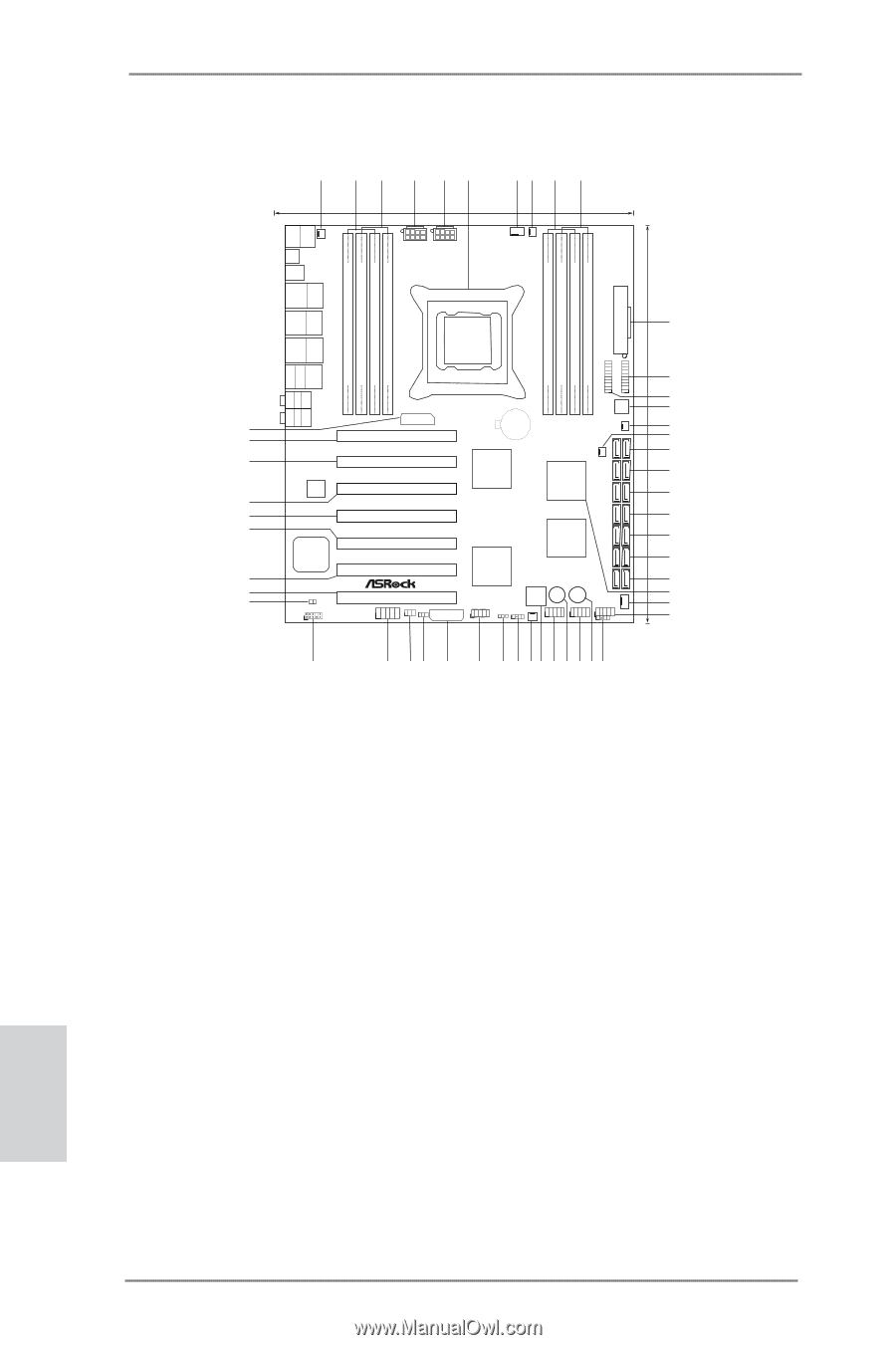
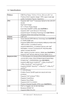
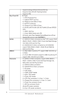
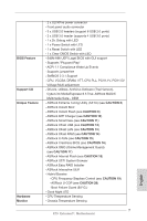
Motherboard Layout 1 2 3 4 5 6 78 9 10 26.7cm (10.5 in) 30.5cm (12.0 in) PS2 Keyboard USB 2.0 T: USB0 B: USB1 PWR_FAN1 Clr CMOS USB 2.0 T: USB2 B: USB3 USB 2.0 T: USB4 Top: B: USB5 RJ-45 ATX12V2 ATX12V1 Designed in Taipei CPU_FAN1 CPU_FAN2 ATXPWR1 DDR3 2400+ 4 Channels DDR3 DDR3_D2 (64 bit, 240-pin module) DDR3_D1 (64 bit, 240-pin module) DDR3_C2 (64 bit, 240-pin module) DDR3_C1 (64 bit, 240-pin module) USB3_6_7 DDR3_A1 (64 bit, 240-pin module) DDR3_A2 (64 bit, 240-pin module) DDR3_B1 (64 bit, 240-pin module) DDR3_B2 (64 bit, 240-pin module) IEEE 1394 USB 2.0 T: USB6 11 B: USB7 USB 3.0 T: USB0 Top: B: USB1 RJ-45 USB 3.0 T: USB2 B: USB3 RoHS 12 USB3_4_5 eSATA eSATA Top: Central/Bass Center: REAR SPK Bottom: Optical SPDIF SLI/XFIRE_PWR1 1 1 13 64Mb BIOS 14 Top: LINE IN Center: FRONT Bottom: MIC IN CHA_FAN3 CMOS 50 Battery 15 49 PCIE1 16 SATA3_0_1 X PCI Express 3.0 Ready Fast RAM SB_FAN1 17 48 PCIE2 PLX SATA2_0_1 LSI SAS 8747 Intel 18 SATA2_2_3 Super I/O PCIE3 X79 19 47 X79 Extreme11 SAS_0_1 46 PCIE4 20 2 oz Copper PCB SAS_2_3 45 Front USB 3.0 LSI 21 Sound CORE3D PCIE5 4-Way SLI PLX 2308 SAS_4_5 22 44 PCIE6 8747 23 SAS_6_7 43 42 HDMI_SPDIF1 1 HD_AUDIO1 1 PCIE7 FRONT_1394 IR1 CLRCMOS1 1 1 3 SLI/XFIRE_PWR2 PANEL1 PLED PWRBTN 1 HDLED RESET Dr. PWRBTN1 Debug CHA_FAN2 PLED1 SPEAKER1 1 1 1 USB_12_13 RSTBTN1 USB_10_11 1 USB_8_9 CHA_FAN1 1 1 CIR1 24 25 26 41 40 39 38 37 36 35 34 33 32 31 30 29 28 27 1 Power Fan Connector (PWR_FAN1) 26 USB 2.0 Header (USB_8_9, Black) 2 2 x 240-pin DDR3 DIMM Slots 27 Consumer Infrared Module Header (DDR3_A1, DDR3_B1, Black) (CIR1, Gray) 3 2 x 240-pin DDR3 DIMM Slots 28 Reset Switch (RSTBTN1) (DDR3_A2, DDR3_B2, Black) 29 USB 2.0 Header (USB_10_11, Black) 4 ATX 12V Power Connector (ATX12V2) 30 Power Switch (PWRBTN1) 5 ATX 12V Power Connector (ATX12V1) 31 USB 2.0 Header (USB_12_13, Black) 6 2011-Pin CPU Socket 32 Dr. Debug 7 CPU Fan Connector (CPU_FAN1) 33 Chassis Fan Connector (CHA_FAN2) 8 CPU Fan Connector (CPU_FAN2) 34 Chassis Speaker Header (SPEAKER1) 9 2 x 240-pin DDR3 DIMM Slots 35 Power LED Header (PLED1) (DDR3_D2, DDR3_C2, Black) 36 System Panel Header (PANEL1, Black) 10 2 x 240-pin DDR3 DIMM Slots 37 SLI / XFIRE Power Connector (DDR3_D1, DDR3_C1, Black) (SLI/XFIRE_PWR2) 11 ATX Power Connector (ATXPWR1) 38 Clear CMOS Jumper (CLRCMOS1) 12 USB 3.0 Header (USB3_4_5, Black) 39 Infrared Module Header (IR1) 13 USB 3.0 Header (USB3_6_7, Black) 40 Front Panel IEEE 1394 Header 14 SPI Flash Memory (64Mb) (FRONT_1394) 15 Chassis Fan Connector (CHA_FAN3) 41 Front Panel Audio Header (HD_AUDIO1) 16 SB Fan Connector (SB_FAN1) 42 HDMI_SPDIF Header (HDMI_SPDIF1) 17 SATA3 Connector (SATA3_0_1, Gray) 43 PCI Express 3.0 x16 Slot (PCIE7, Black) 18 SATA2 Connector (SATA2_0_1, Black) 44 PCI Express 3.0 x16 Slot (PCIE6, Black) 19 SATA2 Connector (SATA2_2_3, Black) 45 PCI Express 3.0 x16 Slot (PCIE5, Black) 20 SAS Connector (SAS_0_1, Gray) 46 PCI Express 3.0 x16 Slot (PCIE4, Black) 21 SAS Connector (SAS_2_3, Gray) 47 PCI Express 3.0 x16 Slot (PCIE3, Black) 22 SAS Connector (SAS_4_5, Gray) 48 PCI Express 3.0 x16 Slot (PCIE2, Black) 23 SAS Connector (SAS_6_7, Gray) 49 PCI Express 3.0 x16 Slot (PCIE1, Black) 24 Intel X79 Chipset 50 SLI / XFIRE Power Connector 25 Chassis Fan Connector (CHA_FAN1) 2 (SLI/XFIRE_PWR1) X79 Extreme11 Motherboard English
-
 1
1 -
 2
2 -
 3
3 -
 4
4 -
 5
5 -
 6
6 -
 7
7 -
 8
8 -
9
-
10
-
11
-
12
-
13
-
14
-
15
-
16
-
17
-
18
-
19
-
20
-
21
-
22
-
23
-
24
-
25
-
26
-
27
-
28
-
29
-
30
-
31
-
32
-
33
-
34
-
35
-
36
-
37
-
38
-
39
-
40
-
41
-
42
-
43
-
44
-
45
-
46
-
47
-
48
-
49
-
50
-
51
-
52
-
53
-
54
-
55
-
56
-
57
-
58
-
59
-
60
-
61
-
62
-
63
-
64
-
65
-
66
-
67
-
68
-
69
-
70
-
71
-
72
-
73
-
74
-
75
-
76
-
77
-
78
-
79
-
80
-
81
-
82
-
83
-
84
-
85
-
86
-
87
-
88
-
89
-
90
-
91
-
92
-
93
-
94
-
95
-
96
-
97
-
98
-
99
-
100
-
101
-
102
-
103
-
104
-
105
-
106
-
107
-
108
-
109
-
110
-
111
-
112
-
113
-
114
-
115
-
116
-
117
-
118
-
119
-
120
-
121
-
122
-
123
-
124
-
125
-
126
-
127
-
128
-
129
-
130
-
131
-
132
-
133
-
134
-
135
-
136
-
137
-
138
-
139
-
140
-
141
-
142
-
143
-
144
-
145
-
146
-
147
-
148
-
149
-
150
-
151
-
152
-
153
-
154
-
155
-
156
-
157
-
158
-
159
-
160
-
161
-
162
-
163
-
164
-
165
-
166
-
167
-
168
-
169
-
170
-
171
-
172
-
173
-
174
-
175
-
176
-
177
-
178
-
179
-
180
-
181
-
182
-
183
-
184
-
185
-
186
-
187
-
188
-
189
-
190
-
191
-
192
-
193
-
194
-
195
-
196
-
197
-
198
-
199
-
200
-
201
-
202
-
203
-
204
-
205
-
206
-
207
-
208
-
209
-
210
-
211
-
212
-
213
-
214
-
215
-
216
-
217
-
218
-
219
-
220
-
221
-
222
-
223
-
224
-
225
-
226
-
227
-
228
-
229
-
230
-
231
-
232
-
233
-
234
-
235
-
236
-
237
-
238
-
239
-
240
-
241
-
242
-
243
-
244
-
245
-
246
-
247
-
248
-
249
-
250
-
251
-
252
-
253
-
254
-
255
-
256
-
257
-
258
-
259
-
260
-
261
-
262
-
263
-
264
-
265
-
266
-
267
-
268
-
269
-
270
 |
 |