ASRock X79 Extreme11 Quick Installation Guide - Page 49
CHA_FAN1, CHA_FAN2
 |
View all ASRock X79 Extreme11 manuals
Add to My Manuals
Save this manual to your list of manuals |
Page 49 highlights
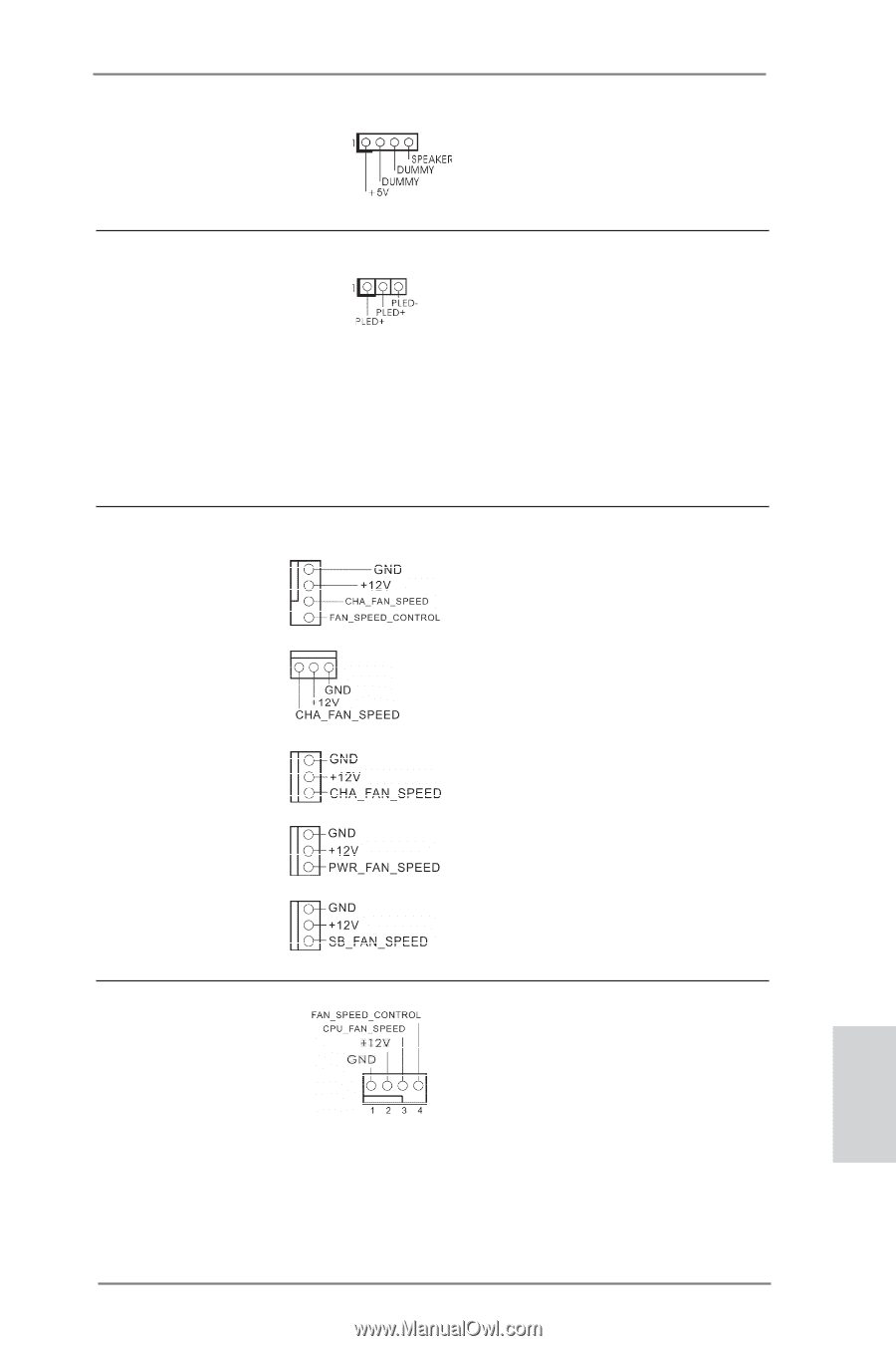
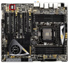
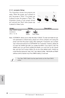
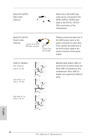
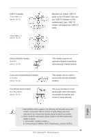
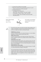
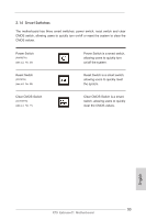
Chassis Speaker Header (4-pin SPEAKER 1) (see p.2, No. 34) Please connect the chassis speaker to this header. Power LED Header (3-pin PLED1) (see p.2, No. 35 Please connect the chassis power LED to this header to indicate system power status. The LED is on when the system is operating. The LED keeps blinking in S1/S3 state. The LED is off in S4 state or S5 state (power off). Chassis, Power and SB Please connect the fan cables Fan Connectors to the fan connectors and match (4-pin CHA_FAN1) the black wire to the ground pin. (see p.2, No. 25) CHA_FAN1, CHA_FAN2 and CHA_FAN3 support Fan (3-pin CHA_FAN2) Control. SB_FAN1 supports (see p.2, No. 33) Quiet Fan. (3-pin CHA_FAN3) (see p.2, No. 15) (3-pin PWR_FAN1) (see p.2, No. 1) (3-pin SB_FAN1) (see p.2, No. 16) CPU Fan Connectors (4-pin CPU_FAN1) (see p.2, No. 7) Please connect the CPU fan cable to the connector and match the black wire to the ground pin. English 49 X79 Extreme11 Motherboard
-
 1
1 -
2
-
3
-
4
-
5
-
6
-
7
-
8
-
9
-
10
-
11
-
12
-
13
-
14
-
15
-
16
-
17
-
18
-
19
-
20
-
21
-
22
-
23
-
24
-
25
-
26
-
27
-
28
-
29
-
30
-
31
-
32
-
33
-
34
-
35
-
36
-
37
-
38
-
39
-
40
-
41
-
42
-
43
-
 44
44 -
 45
45 -
 46
46 -
 47
47 -
 48
48 -
 49
49 -
 50
50 -
 51
51 -
 52
52 -
 53
53 -
 54
54 -
55
-
56
-
57
-
58
-
59
-
60
-
61
-
62
-
63
-
64
-
65
-
66
-
67
-
68
-
69
-
70
-
71
-
72
-
73
-
74
-
75
-
76
-
77
-
78
-
79
-
80
-
81
-
82
-
83
-
84
-
85
-
86
-
87
-
88
-
89
-
90
-
91
-
92
-
93
-
94
-
95
-
96
-
97
-
98
-
99
-
100
-
101
-
102
-
103
-
104
-
105
-
106
-
107
-
108
-
109
-
110
-
111
-
112
-
113
-
114
-
115
-
116
-
117
-
118
-
119
-
120
-
121
-
122
-
123
-
124
-
125
-
126
-
127
-
128
-
129
-
130
-
131
-
132
-
133
-
134
-
135
-
136
-
137
-
138
-
139
-
140
-
141
-
142
-
143
-
144
-
145
-
146
-
147
-
148
-
149
-
150
-
151
-
152
-
153
-
154
-
155
-
156
-
157
-
158
-
159
-
160
-
161
-
162
-
163
-
164
-
165
-
166
-
167
-
168
-
169
-
170
-
171
-
172
-
173
-
174
-
175
-
176
-
177
-
178
-
179
-
180
-
181
-
182
-
183
-
184
-
185
-
186
-
187
-
188
-
189
-
190
-
191
-
192
-
193
-
194
-
195
-
196
-
197
-
198
-
199
-
200
-
201
-
202
-
203
-
204
-
205
-
206
-
207
-
208
-
209
-
210
-
211
-
212
-
213
-
214
-
215
-
216
-
217
-
218
-
219
-
220
-
221
-
222
-
223
-
224
-
225
-
226
-
227
-
228
-
229
-
230
-
231
-
232
-
233
-
234
-
235
-
236
-
237
-
238
-
239
-
240
-
241
-
242
-
243
-
244
-
245
-
246
-
247
-
248
-
249
-
250
-
251
-
252
-
253
-
254
-
255
-
256
-
257
-
258
-
259
-
260
-
261
-
262
-
263
-
264
-
265
-
266
-
267
-
268
-
269
-
270
 |
 |