ASRock X99 Extreme4/3.1 User Manual
ASRock X99 Extreme4/3.1 Manual
 |
View all ASRock X99 Extreme4/3.1 manuals
Add to My Manuals
Save this manual to your list of manuals |
ASRock X99 Extreme4/3.1 manual content summary:
- ASRock X99 Extreme4/3.1 | User Manual - Page 1
X99 Extreme4/3.1 User Manual - ASRock X99 Extreme4/3.1 | User Manual - Page 2
change without notice, and should not be constructed as a commitment by ASRock. ASRock assumes no responsibility for any errors or omissions that may appear in CALIFORNIA, USA ONLY he Lithium battery adopted on this motherboard contains Perchlorate, a toxic substance controlled in Perchlorate Best - ASRock X99 Extreme4/3.1 | User Manual - Page 3
Manufactured under license under U.S. Patent Nos: 5,956,674; 5,974,380; 6,487,535; 7,003,467 & other U.S. and worldwide patents issued & pending. DTS, the Symbol, & DTS and the Symbol together is a registered trademark & DTS Connect, DTS Interactive, DTS Neo:PC are trademarks of DTS, Inc. Product - ASRock X99 Extreme4/3.1 | User Manual - Page 4
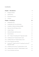
1 Introduction 1 1.1 Package Contents 1 1.2 Speciications 2 1.3 Motherboard Layout 6 1.4 I/O Panel 8 Chapter 2 Installation 10 2.1 Smart Switches 26 2.8 SLITM , 3-Way SLITMand Quad SLITM Operation Guide 27 2.8.1 Installing Two SLITM-Ready Graphics Cards 27 2.8.2 Installing - ASRock X99 Extreme4/3.1 | User Manual - Page 5
36 2.11 HDD Saver Cable Installation Guide 39 2.12 ASRock USB 3.1/A+C Installation Guide 40 Chapter 3 Software and Utilities Operation 42 3.1 Installing Drivers 42 3.2 A-Tuning 43 3.3 ASRock APP Shop 49 3.3.1 UI Overview 49 3.3.2 Apps 50 3.3.3 BIOS & Drivers 53 3.3.4 Setting 54 - ASRock X99 Extreme4/3.1 | User Manual - Page 6
4.4.6 USB Coniguration 79 4.4.7 Trusted Computing 81 4.5 Tools 82 4.6 Hardware Health Event Monitoring Screen 87 4.7 Security Screen 89 4.8 Boot Screen 90 4.9 Exit Screen 93 - ASRock X99 Extreme4/3.1 | User Manual - Page 7
website as well. ASRock website http://www.asrock.com. 1.1 Package Contents • ASRock X99 Extreme4/3.1 Motherboard (ATX Form Factor) • ASRock X99 Extreme4/3.1 Quick Installation Guide • ASRock X99 Extreme4/3.1 Support CD • 1 x I/O Panel Shield • 1 x ASRock USB 3.1/A+C • 1 x ASRock SLI_Bridge_2S Card - ASRock X99 Extreme4/3.1 | User Manual - Page 8
Untied Overclocking Technology Chipset • Intel® X99 Memory • Quad Channel DDR4 Memory Technology • 8 x DDR4 DIMM Slots • Supports DDR4 3200+(OC)*/2933(OC)/2800(OC)/2400 (OC)/2133 non-ECC, un-bufered memory * Please refer to Memory Support List on ASRock's website for more information. (http - ASRock X99 Extreme4/3.1 | User Manual - Page 9
X99 Extreme4/3.1 * If you install CPU with 28 lanes, 3-Way SLITM is not supported. To support 3-Way SLITM, x Optical SPDIF Out Port • 4 x USB 2.0 Ports (Supports ESD Protection (ASRock Full Spike Protection)) • 4 x USB 3.0 Ports (Supports ESD Protection (ASRock Full Spike Protection)) • 1 x RJ - ASRock X99 Extreme4/3.1 | User Manual - Page 10
Headers (support 4 USB 2.0 ports) (Supports ESD Protection (ASRock Full Spike Protection)) • 1 x USB 3.0 Header (Supports 2 USB 3.0 ports) (Supports ESD Protection (ASRock Full Spike Protection)) English BIOS Feature • 2 x 128Mb AMI UEFI Legal BIOS with multilingual GUI support (1 x Main BIOS and - ASRock X99 Extreme4/3.1 | User Manual - Page 11
X99 Extreme4/3.1 Hardware Monitor OS Certiications • ACPI 1.1 Compliant wake up events • SMBIOS 2.3.1 Support visit our website: http://www.asrock.com Please realize that there is a certain risk involved with overclocking adjusting the setting in the BIOS, applying Untied Overclocking Technology, - ASRock X99 Extreme4/3.1 | User Manual - Page 12
CT3 CT2 CT1 X99 Extreme4/3.1 PCIE2 30 Purity SoundTM 2 PCI Express 3.0 RoHS PCIE3 1 T BT1 PCIE4 CMOS Battery Super USB 3.1 I/O PCIE5 X99 SATA3_2_5 SATAE_1 BIOS_A_LED CHA_FAN2 SATA_PWR_1 1 PLED1 CHA_FAN1 1 1 SPEAKER1 BIOS_B_LED PLED PWRBTN 128Mb BIOS BIOS_A 128Mb BIOS - ASRock X99 Extreme4/3.1 | User Manual - Page 13
USB 2.0 Header (USB6_7) 25 BIOS Selection Jumper (BIOS_SEL1) 26 Clear CMOS Jumper (CLRCMOS1) 27 COM Port Header (COM1) 28 TPM Header (TPMS1) 29 Front Panel Audio Header (HD_AUDIO1) 30 hunderbolt AIC Connector (TBT1) 31 PCIe Power Connector (PCIE_PWR1) 32 Power Fan Connector (PWR_FAN1) X99 Extreme4 - ASRock X99 Extreme4/3.1 | User Manual - Page 14
Speaker (Black) 6 Line In (Light Blue) 7 Front Speaker (Lime)** 8 Microphone (Pink) 12 11 10 98 No. Description 9 Optical SPDIF Out Port 10 USB 3.0 Ports (USB3_23) 11 USB 3.0 Ports (USB3_01) 12 eSATA Connector*** 13 USB 2.0 Ports (USB01) 14 Clear CMOS Switch 15 PS/2 Keyboard Port English 8 - ASRock X99 Extreme4/3.1 | User Manual - Page 15
X99 Extreme4/3.1 * here are two LEDs on each LAN port. Please refer to the table below for the , or select "Realtek HDA Audio 2nd output" to use the front panel audio. *** he eSATA connector supports SATA with cables within 1 meters. he S_SATA3_3 connector is shared with the eSATA port English 9 - ASRock X99 Extreme4/3.1 | User Manual - Page 16
2 Installation his is an ATX form factor motherboard. Before you install the motherboard, study the coniguration of your chassis to ensure that the motherboard its into it. Pre-installation Precautions Take note of the following precautions before you install motherboard components or change any - ASRock X99 Extreme4/3.1 | User Manual - Page 17
X99 Extreme4/3.1 2.1 Installing the CPU 1. Before you insert the 2011-3-Pin CPU will be seriously damaged. 2. Unplug all power cables before installing the CPU. CAUTION: Please note that X99 platform is only compatible with the LGA 2011-3 socket, which is incompatible with the LGA 2011 socket (for - ASRock X99 Extreme4/3.1 | User Manual - Page 18
A 3 B 4 5 12 English - ASRock X99 Extreme4/3.1 | User Manual - Page 19
X99 Extreme4/3.1 6 A B 7 A B 8 Please save and replace the cover if the processor is removed. he cover must be placed if you wish to return the motherboard for ater service. 13 English - ASRock X99 Extreme4/3.1 | User Manual - Page 20
2.2 Installing the CPU Fan and Heatsink 1 14 2 CPU_FAN English - ASRock X99 Extreme4/3.1 | User Manual - Page 21
X99 Extreme4/3.1 2.3 Installation of Memory Modules (DIMM) his motherboard provides eight 288-pin DDR4 (Double Data Rate 4) DIMM slots, and supports Quad Channel Memory Technology. 1. For quad channel coniguration, you always need to install identical (the same brand, speed, size and chip-type) - ASRock X99 Extreme4/3.1 | User Manual - Page 22
1 2 3 16 English - ASRock X99 Extreme4/3.1 | User Manual - Page 23
X99 Extreme4/3.1 2.4 Expansion Slots (PCI Express Slots) here are 5 PCI Express slots on the motherboard. Before installing an expansion card, please make sure that the power supply is switched of or the power cord is unplugged. Please read the documentation - ASRock X99 Extreme4/3.1 | User Manual - Page 24
in 3-Way CrossFireXTM Mode x16 N/A x8 N/A x4 *3-Way SLITM Mode is not supported for CPU with 28 PCIe lanes. For a better thermal environment, please connect a chassis fan to the motherboard's chassis fan connector (CHA_FAN1, CHA_FAN2 or CHA_FAN3) when using multiple graphics cards. English - ASRock X99 Extreme4/3.1 | User Manual - Page 25
X99 Extreme4/3.1 2.5 Jumpers Setup he illustration shows how jumpers are setup. When the jumper 5 seconds. However, please do not clear the CMOS right ater you update the BIOS. If you need to clear the CMOS when you just inish updating the BIOS, you must boot up the system irst, and then shut it down - ASRock X99 Extreme4/3.1 | User Manual - Page 26
pin1 and pin2 again, then use "Secure Backup UEFI" in BIOS setup utility to copy the BIOS ile to the main BIOS to ensure normal system operation. For the sake of system safety, users cannot update the backup BIOS manually. Users may refer to the BIOS LED (BIOS_A_LED or BIOS_B_LED) to identify which - ASRock X99 Extreme4/3.1 | User Manual - Page 27
X99 Extreme4/3.1 2.6 Onboard Headers and Connectors Onboard headers and connectors are NOT jumpers. Do NOT place jumper caps over these headers and connectors. Placing jumper caps over the headers and connectors will cause permanent damage to the motherboard. System Panel Header (9-pin PANEL1) (see - ASRock X99 Extreme4/3.1 | User Manual - Page 28
PLEDPLED+ PLED+ SATA3_3 S_SATA3_3 S_SATA3_1 Please connect the chassis power LED to this header to indicate the system's power status. hese ten SATA3 connectors support SATA data cables for internal storage devices with up to 6.0 Gb/s data transfer rate. If the eSATA port on the rear I/O has been - ASRock X99 Extreme4/3.1 | User Manual - Page 29
X99 Extreme4/3.1 USB 2.0 Headers (9-pin USB4_5) (see p.6, No. 23) (9-pin USB6_7) (see p.6, No. 24) USB_PWR PP+ GND DUMMY 1 GND P+ PUSB_PWR Besides four USB 2.0 ports on the I/O panel, there are two headers on this motherboard. Each USB 2.0 header can support two ports. USB 3.0 Header (19-pin - ASRock X99 Extreme4/3.1 | User Manual - Page 30
pin ATX12V1) (see p.6, No. 3) 1 13 8 5 4 1 his motherboard provides a 24-pin ATX power connector. To use a 20-pin ATX power supply, please plug it along Pin 1 and Pin 13. his motherboard provides an 8-pin ATX 12V power connector. To use a 4-pin ATX power supply, please plug it along Pin 1 and - ASRock X99 Extreme4/3.1 | User Manual - Page 31
X99 Extreme4/3.1 PCIe Power Connector (4-pin PCIE_PWR1) (see p.6, No. 31) Please connector via the GPIO cable. RRXD1 DDTR#1 DDSR#1 CCTS#1 1 RRI#1 RRTS#1 GND TTXD1 DDCD#1 his COM1 header supports a serial port module. TPM Header (17-pin TPMS1) (see p.6, No. 28) 1 GN D SMB_CLK_MAIN SMB_DATA_MAIN - ASRock X99 Extreme4/3.1 | User Manual - Page 32
2.7 Smart Switches he motherboard has a Clear CMOS Switch, allowing users to clear the CMOS values. Clear CMOS Switch (CLRCBTN) (see p.8, No. 14) Clear CMOS Switch allows users to quickly - ASRock X99 Extreme4/3.1 | User Manual - Page 33
X99 Extreme4/3.1 2.8 SLITM , 3-Way SLITMand Quad SLITM Operation Guide his motherboard supports NVIDIA® SLITM , 3-Way SLITM and Quad SLITM (Scalable Link Interface) technology that allows you to install up to three identical PCI Express x16 graphics cards. - ASRock X99 Extreme4/3.1 | User Manual - Page 34
SLI_ Bridge_2S Card to the goldingers on each graphics card. Make sure the ASRock SLI_ Bridge_2S Card is irmly in place. SLI_Bridge_2S Card ASRock SLI_Bridge_2S Card Step 4 Connect a VGA cable or a DVI cable to the monitor connector or the DVI connector of the graphics card that is inserted to - ASRock X99 Extreme4/3.1 | User Manual - Page 35
X99 Extreme4/3.1 2.8.2 Installing Three SLITM-Ready Graphics Cards Step 1 Insert one graphics on the three graphics cards. Step 3 Align and insert the ASRock 3-Way SLI2S1S Bridge Card to the goldingers on each graphics card. Make sure the ASRock 3-Way SLI-2S1S Bridge Card is irmly in place. 3-Way - ASRock X99 Extreme4/3.1 | User Manual - Page 36
Step 4 Connect a VGA cable or a DVI cable to the monitor connector or the DVI connector of the graphics card that is inserted to PCIE1 slot. 30 English - ASRock X99 Extreme4/3.1 | User Manual - Page 37
X99 Extreme4/3.1 2.8.3 Driver Installation and Setup Install the graphics card drivers to your system. Ater that, you can enable the Multi-Graphics Processing Unit (GPU) in the - ASRock X99 Extreme4/3.1 | User Manual - Page 38
, 3-Way CrossFireXTM and Quad CrossFireXTM Operation Guide his motherboard supports CrossFireXTM, 3-way CrossFireXTM and Quad CrossFireXTM to enable CrossFireXTM. Please refer to AMD graphics card manuals for detailed installation guide. 2.9.1 Installing Two CrossFireXTM-Ready Graphics Cards Step 1 - ASRock X99 Extreme4/3.1 | User Manual - Page 39
X99 Extreme4/3.1 Step 3 Connect a VGA cable or a DVI cable to the monitor connector or the DVI connector of the graphics card that is inserted to PCIE1 slot. 33 English - ASRock X99 Extreme4/3.1 | User Manual - Page 40
to connect the graphics cards on PCIE3 and PCIE5 slots. (he CrossFire Bridge is provided with the graphics card you purchase, not bundled with this motherboard. Please refer to your graphics card vendor for details.) Step 3 Connect a VGA cable or a DVI cable to the monitor connector or the DVI - ASRock X99 Extreme4/3.1 | User Manual - Page 41
X99 Extreme4/3.1 2.9.3 Driver Installation and Setup Step 1 Power on your computer and boot previously installed Catalyst drivers prior to installation. Please check AMD's website for AMD driver updates. Step 3 Install the required drivers and CATALYST Control Center then restart your computer. - ASRock X99 Extreme4/3.1 | User Manual - Page 42
2.10 M.2_SSD (NGFF) Module Installation Guide he M.2, also known as the Next Generation Form Factor (NGFF), is a small size and versatile card edge connector that aims to replace mPCIe and mSATA. - ASRock X99 Extreme4/3.1 | User Manual - Page 43
B A C B A E D C B A E D NUT2 NUT1 X99 Extreme4/3.1 Step 3 Move the standof based on the module type and length. he the nut to be used. Hand tighten the standof into the desired nut location on the motherboard. Step 5 Align and gently insert the M.2 (NGFF) SSD module into the M.2 slot. - ASRock X99 Extreme4/3.1 | User Manual - Page 44
M.2_SSD (NGFF) Module Support List PCIe Interface SATA Interface Plextor PX-G512M6e Plextor PX-G256M6e SanDisk SSDSCKGW080A401/80G Kingston RBU-SM2280S3/120G For the latest updates of M.2_SSD (NFGG) module support list, please visit our website for details: http://www.asrock.com English 38 - ASRock X99 Extreme4/3.1 | User Manual - Page 45
X99 Extreme4/3.1 2.11 HDD Saver Cable Installation Guide The HDD Saver Connector on this motherboard allows you to switch on SATA HDD(s). * he HDD Saver Connector supports up to two SATA HDDs. 2. Connect one end of the SATA data cable to a SATA port on the motherboard. hen connect the other end to - ASRock X99 Extreme4/3.1 | User Manual - Page 46
, we suggest using the Type-A connectors on your motherboard. • 1 x USB 3.1 Type-C Port (Supports ESD Protection (ASRock Full Spike Protection)) * his port supports power outputs up to 5V/3A. For charging Type-C USB devices, the device should support Type-C standards to adjust the current because it - ASRock X99 Extreme4/3.1 | User Manual - Page 47
X99 Extreme4/3.1 Installation Procedure he ASRock USB 3.1/A+C provides two external USB 3.1 ports which support transfer rates up to 10 Gbps. Follow the simple steps below to install the ASRock USB on your motherboard and remove its slot bracket. *To maximize the performance of ASRock USB 3.1/A+C, it - ASRock X99 Extreme4/3.1 | User Manual - Page 48
drivers. herefore, the drivers you install can work properly. Utilities Menu he Utilities Menu shows the application sotware that the motherboard supports. Click on a speciic item then follow the installation wizard to install it. To improve Windows 7 compatibility, please download and install - ASRock X99 Extreme4/3.1 | User Manual - Page 49
X99 Extreme4/3.1 3.2 A-Tuning A-Tuning is ASRock When you install the all-in-one driver to your system from ASRock's support CD, A-Tuning will be auto-installed as well. Ater the installation , System Info, Live Update, Tech Service and Settings. Operation Mode Choose an operation mode for your - ASRock X99 Extreme4/3.1 | User Manual - Page 50
program's priority highest. Fast Boot Fast Boot minimizes your computer's boot time. Please note that Ultra Fast mode is only supported by Windows 8.1/8 and the VBIOS must support UEFI GOP if you are using an external graphics card. OMG Schedule the starting and ending hours of Internet access - ASRock X99 Extreme4/3.1 | User Manual - Page 51
X99 Extreme4/3.1 FAN-Tastic Tuning Conigure up to ive diferent fan speeds using the graph. he fans will automatically shit to the next speed level when the assigned temperature is met. Dehumidiier Prevent motherboard SSD and optical disk drives are all supported. he health status block displays Good - ASRock X99 Extreme4/3.1 | User Manual - Page 52
OC Tweaker Conigurations for overclocking the system. System Info View information about the system. *he System Browser tab may not appear for certain models. 46 English - ASRock X99 Extreme4/3.1 | User Manual - Page 53
Live Update Check for newer versions of BIOS or drivers. X99 Extreme4/3.1 Tech Service Contact Tech Service if you have problems with your computer. Please leave your contact information along with details of the problem. English 47 - ASRock X99 Extreme4/3.1 | User Manual - Page 54
Settings Conigure ASRock A-Tuning. Click to select "Auto run at Windows Startup" if you want A-Tuning to be launched when you start up the Windows operating system. 48 English - ASRock X99 Extreme4/3.1 | User Manual - Page 55
X99 Extreme4/3.1 3.3 ASRock APP Shop he ASRock APP Shop is an online store for purchasing and downloading sotware applications for your ASRock computer. You can install various apps and support utilities quickly and easily, and optimize your system and keep your motherboard up to date simply with a - ASRock X99 Extreme4/3.1 | User Manual - Page 56
3.3.2 Apps When the "Apps" tab is selected, you will see all the available apps on screen for you to download. Installing an App Step 1 Find the app you want to install. he most recommended app appears on the let side of the screen. he other various apps are shown on the right. Please scroll up and - ASRock X99 Extreme4/3.1 | User Manual - Page 57
X99 Extreme4/3.1 Step 3 If you want to install the app, click on the red icon to start downloading. Step 4 When installation completes, you can ind the green " - ASRock X99 Extreme4/3.1 | User Manual - Page 58
Upgrading an App You can only upgrade the apps you have already installed. When there is an available new version for your app, you will ind the mark of "New Version" appears below the installed app icon. Step 1 Click on the app icon to see more details. Step 2 Click on the yellow icon to start - ASRock X99 Extreme4/3.1 | User Manual - Page 59
X99 Extreme4/3.1 3.3.3 BIOS & Drivers Installing BIOS or Drivers When the "BIOS & Drivers" tab is selected, you will see a list of recommended or critical updates for the BIOS or drivers. Please update them all soon. Step 1 Please check the item information before update. Click on Step 2 to see - ASRock X99 Extreme4/3.1 | User Manual - Page 60
3.3.4 Setting In the "Setting" page, you can change the language, select the server location, and determine if you want to automatically run the ASRock APP Shop on Windows startup. 54 English - ASRock X99 Extreme4/3.1 | User Manual - Page 61
X99 Extreme4/3.1 3.4 Start8 For those Windows 8 users who miss the Start Menu, Start8 Installing Start8 Install Start8, which is located in the folder at the following path of the Support CD: \ ASRock Utility > Start8. 3.4.2 Coniguring Start8 Style Select between the Windows 7 style and Windows 8 - ASRock X99 Extreme4/3.1 | User Manual - Page 62
Conigure Conigure provides coniguration options, including icon sizes, which shortcuts you want Start Menu to display, quick access to recently used apps, the functionality of the power button, and more. Control 56 English - ASRock X99 Extreme4/3.1 | User Manual - Page 63
X99 Extreme4/3.1 Control lets you conigure what a click on the start button or a press on the Windows key does. Desktop Desktop allows you to disable the hot - ASRock X99 Extreme4/3.1 | User Manual - Page 64
test routines. If you wish to enter the UEFI SETUP UTILITY ater POST, restart the system by pressing + + , or by pressing the reset button on the system chassis. You may also restart by turning the system of and then back on. Because the UEFI sotware is constantly being updated - ASRock X99 Extreme4/3.1 | User Manual - Page 65
X99 Extreme4/3.1 4.1.2 Navigation Keys Use < > key or < > key to choose among the selections on the menu bar, and use < > key or < > key to move the cursor up - ASRock X99 Extreme4/3.1 | User Manual - Page 66
4.2 Main Screen When you enter the UEFI SETUP UTILITY, the Main screen will appear and display the system overview. My Favorite Display your collection of BIOS items. Press F5 to add/remove your favorite items. 60 English - ASRock X99 Extreme4/3.1 | User Manual - Page 67
, you can set up overclocking features. X99 Extreme4/3.1 Because the UEFI sotware is constantly being updated, the following UEFI setup screens and descriptions setting. Please note that overclocking may cause damage to your CPU and motherboard. It should be done at your own risk and expense. Load - ASRock X99 Extreme4/3.1 | User Manual - Page 68
and clock speed of other components are too high. Spread Spectrum Enable Spread Spectrum to reduce electromagnetic interference for passing EMI tests. Disable to achieve higher clock speeds when overclocking. SB Spread Spectrum Enable SB Spread Spectrum to reduce electromagnetic interference for - ASRock X99 Extreme4/3.1 | User Manual - Page 69
X99 Extreme4/3.1 Long Duration Power Limit Conigure Package Power Limit 1 in watts. When the limit is exceeded, the CPU ratio will be lowered ater a period of time. A - ASRock X99 Extreme4/3.1 | User Manual - Page 70
Voltage. he default value is [Auto]. DRAM Reference Clock Select Auto for optimized settings. DRAM Frequency If [Auto] is selected, the motherboard will detect the memory module(s) inserted and assign the appropriate frequency automatically. DRAM Frequency OC Preset If the DRAM frequency is selected - ASRock X99 Extreme4/3.1 | User Manual - Page 71
X99 Extreme4/3.1 Refresh Cycle Time (tRFC) he number of clocks from a Refresh command until the irst Activate command to the same rank. RAS to RAS Delay (tRRD) - ASRock X99 Extreme4/3.1 | User Manual - Page 72
tCCCD_L Conigure back to back CAS to CAS (i.e. READ to RAED or WRITE to WRITE) from same rank separation parameter. tCCCD_WR_L Conigure back to back CAS to CAS (i.e. READ to RAED or WRITE to WRITE) from same rank separation parameter. tRWSR Conigure READ to WRITE same rank dead cycle Back to back - ASRock X99 Extreme4/3.1 | User Manual - Page 73
X99 Extreme4/3.1 tRRDR Conigure Read to Read diferent rank dead cycle Back to on die termination resistors' PARK for channel A. ODT NOM (CH A) Use this to change ODT (CH A) Auto/Manual settings. he default is [Auto]. ODT WR (CH B) Conigure the memory on die termination resistors' WR for channel - ASRock X99 Extreme4/3.1 | User Manual - Page 74
MRC Fast Boot Enable Memory Fast Boot to skip DRAM memory training for booting faster. Memory Test Enable/disable memory test during normal boot. Memory Test On Fast Boot Enable/disable memory test during fast boot. Memory Power Savings Mode Conigure CKE and related memory power savings features. - ASRock X99 Extreme4/3.1 | User Manual - Page 75
X99 Extreme4/3.1 CPU Integrated VR Eiciency Mode Enable FIVR Eiciency Management for power saving. Disable for better performance and overclocking capabilities. Voltage Coniguration Power Saving Mode Enable - ASRock X99 Extreme4/3.1 | User Manual - Page 76
Storage Coniguration, Super IO Coniguration, ACPI Coniguration, USB Coniguration and Trusted Computing. Active Page on Entry Select resolution will be set to 1920 x 1080 if the monitor supports Full HD resolution. If the monitor does not support Full HD resolution, then the resolution will be set to - ASRock X99 Extreme4/3.1 | User Manual - Page 77
4.4.1 CPU Coniguration X99 Extreme4/3.1 Intel Hyper Threading Technology Intel Hyper hreading Technology allows multiple threads to run on each core, so that the overall performance on threaded sotware is - ASRock X99 Extreme4/3.1 | User Manual - Page 78
and C7 all enabled for better power saving. Package C State Support Enable CPU, PCIe, Memory, Graphics C State Support for power saving. CPU C3 State Support Enable C3 sleep state for lower power consumption. CPU C6 State Support Enable C6 deep sleep state for lower power consumption. Enhanced Halt - ASRock X99 Extreme4/3.1 | User Manual - Page 79
4.4.2 Chipset Coniguration X99 Extreme4/3.1 Intel(R) Thunderbolt Enable/Disable the Intel(R) hunderbolt function. function is only applied to system that supports 64-bit PCI decoding. SR-IOV Support Enable/disable the SR-IOV (Single Root IO Virtualization Support) if the system has SR-IOV capable - ASRock X99 Extreme4/3.1 | User Manual - Page 80
his option enables/disables the ASPM support for all PCH downstream devices PCH DMI ASPM Support his option enables/disables the ASPM support for all PCH DMI devices. Intel® Smart Connect Technology Intel® Smart Connect Technology automatically updates your email and social networks, such as Twitter - ASRock X99 Extreme4/3.1 | User Manual - Page 81
X99 Extreme4/3.1 Restore on AC/Power Loss Select the power state ater a power failure. If [Power Of] is selected, the power will remain of when the power - ASRock X99 Extreme4/3.1 | User Manual - Page 82
4.4.3 Storage Coniguration Hard Disk S.M.A.R.T. S.M.A.R.T stands for Self-Monitoring, Analysis, and Reporting Technology. It is a monitoring system for computer hard disk drives to detect and report on various indicators of reliability. 76 English - ASRock X99 Extreme4/3.1 | User Manual - Page 83
4.4.4 Super IO Coniguration X99 Extreme4/3.1 Serial Port Enable or disable the Serial port. Serial Port Address Select the address of the Serial port. 77 English - ASRock X99 Extreme4/3.1 | User Manual - Page 84
By OS to let it be handled by your operating system. USB Keyboard/Remote Power On Allow the system to be waked up by an USB keyboard or remote controller. USB Mouse Power On Allow the system to be waked up by an USB mouse. PCIE Devices Power On Allow the system to be - ASRock X99 Extreme4/3.1 | User Manual - Page 85
4.4.6 USB Coniguration X99 Extreme4/3.1 USB Controller Enable or disable all the USB ports. Intel USB 3.0 Mode Select Intel® USB 3.0 controller mode. Set [Smart Auto] to keep the USB 3.0 driver enabled ater rebooting (USB 3.0 is enabled in BIOS). Set [Auto] to automatically enable the USB 3.0 - ASRock X99 Extreme4/3.1 | User Manual - Page 86
USB Compatibility Patch If your USB devices (i.e. USB mouse or storage) encounter compatibility problems, please enable this option to ix it. Please note that ater enabling this option, it is normal that the system will postpone booting up ater pressing the power button. 80 English - ASRock X99 Extreme4/3.1 | User Manual - Page 87
4.4.7 Trusted Computing X99 Extreme4/3.1 Security Device Support Enable or disable BIOS support for security device. English 81 - ASRock X99 Extreme4/3.1 | User Manual - Page 88
4.5 Tools System Browser ASRock System Browser shows the overview of your current PC and the devices connected. OMG (Online Management Guard) Administrators are able to establish an internet curfew - ASRock X99 Extreme4/3.1 | User Manual - Page 89
X99 Extreme4/3.1 Dehumidiier CPU Fan Setting Conigure the speed of the CPU fan while . Set [Disabled] to switch of the HDD Saver. It is recommended to enable the AHCI Mode to fully support the HDD Saver. You can also enable/disable the HDD Saver via the HDD Saver application under your OS. - ASRock X99 Extreme4/3.1 | User Manual - Page 90
from our support CD, Easy Driver Installer is a handy tool in the UEFI that installs the LAN driver to your system via an USB storage device, then downloads and installs the other required drivers automatically. UEFI Tech Service Contact ASRock Tech Service if you are having trouble with your - ASRock X99 Extreme4/3.1 | User Manual - Page 91
X99 Extreme4/3.1 Boot Manager Enable/disable the Boot Manager. Boot Manager Timeout Enable/disable the Boot Manager Timeout. Timeout Seconds Conigure the number of seconds to wait for the Boot Manager. Instant Flash Save UEFI iles in your USB storage device and run Instant Flash to update your UEFI. - ASRock X99 Extreme4/3.1 | User Manual - Page 92
Network Coniguration Use this to conigure internet connection settings for Internet Flash. Internet Setting Enable or disable sound efects in the setup utility. UEFI Download Server Select a server to download the UEFI irmware. 86 English - ASRock X99 Extreme4/3.1 | User Manual - Page 93
X99 Extreme4/3.1 4.6 Hardware Health Event Monitoring Screen his section allows you to monitor the status of the hardware on your system, including the parameters of the CPU temperature, motherboard temperature, fan speed and voltage. FAN-Tastic Tuning Conigure up to ive diferent fan speeds using - ASRock X99 Extreme4/3.1 | User Manual - Page 94
3 Temp Source Select a fan temperature source for Chassis Fan 3. Over Temperature Protection When Over Temperature Protection is enabled, the system automatically shuts down when the motherboard is overheated. 88 English - ASRock X99 Extreme4/3.1 | User Manual - Page 95
X99 Extreme4/3.1 4.7 Security Screen In this section you may set or change the supervisor/user password for the system. You may also clear Utility. Leave it blank and press enter to remove the password. Secure Boot Use this item to enable or disable support for Windows 8.1/8 Secure Boot. 89 English - ASRock X99 Extreme4/3.1 | User Manual - Page 96
. Fast Boot Fast Boot minimizes your computer's boot time. In fast mode you may not boot from an USB storage device. Ultra Fast mode is only supported by Windows 8.1/8 and the VBIOS must support UEFI GOP if you are using an external graphics card. Please notice that Ultra Fast mode will boot so - ASRock X99 Extreme4/3.1 | User Manual - Page 97
X99 Extreme4/3.1 Full Screen Logo Enable to display the boot logo or disable restores the default settings. CSM (Compatibility Support Module) CSM Enable to launch the Compatibility Support Module. Please do not disable unless you're running a WHCK test. If you are using Windows 8.1/8 64 - ASRock X99 Extreme4/3.1 | User Manual - Page 98
Launch Storage OpROM Policy Select UEFI only to run those that support UEFI option ROM only. Select Legacy only to run those that support legacy option ROM only. Do not launch? Launch Video OpROM Policy Select UEFI only to run those that support UEFI option ROM only. Select Legacy only to run those - ASRock X99 Extreme4/3.1 | User Manual - Page 99
4.9 Exit Screen X99 Extreme4/3.1 Save Changes and Exit When you select this option the following message, "Save coniguration changes and exit setup?" will pop out. Select [OK] to save - ASRock X99 Extreme4/3.1 | User Manual - Page 100
or want to know more about ASRock, you're welcome to visit ASRock's website at http://www.asrock.com; or you may contact your dealer for further information. For technical questions, please submit a support request form at http://www.asrock.com/support/tsd.asp ASRock Incorporation 2F., No.37, Sec
-
 1
1 -
 2
2 -
 3
3 -
 4
4 -
 5
5 -
 6
6 -
 7
7 -
8
-
9
-
10
-
11
-
12
-
13
-
14
-
15
-
16
-
17
-
18
-
19
-
20
-
21
-
22
-
23
-
24
-
25
-
26
-
27
-
28
-
29
-
30
-
31
-
32
-
33
-
34
-
35
-
36
-
37
-
38
-
39
-
40
-
41
-
42
-
43
-
44
-
45
-
46
-
47
-
48
-
49
-
50
-
51
-
52
-
53
-
54
-
55
-
56
-
57
-
58
-
59
-
60
-
61
-
62
-
63
-
64
-
65
-
66
-
67
-
68
-
69
-
70
-
71
-
72
-
73
-
74
-
75
-
76
-
77
-
78
-
79
-
80
-
81
-
82
-
83
-
84
-
85
-
86
-
87
-
88
-
89
-
90
-
91
-
92
-
93
-
94
-
95
-
96
-
97
-
98
-
99
-
100
 |
 |

X99 Extreme4
/
3.1
X99 Extreme4
/
3.1
User Manual