Acer AL2423W AL2423W LCD Monitor
Acer AL2423W Manual
 |
View all Acer AL2423W manuals
Add to My Manuals
Save this manual to your list of manuals |
Acer AL2423W manual content summary:
- Acer AL2423W | AL2423W LCD Monitor - Page 1
Acer AL2423 W Service Guide Service guide files and updates are available on the CSD web: for more information, Please refer to http://csd.acer.com.tw/ 100% Recycled Paper - 1 - - Acer AL2423W | AL2423W LCD Monitor - Page 2
purpose, Any Acer Incorporated software described in this manual is sold or licensed "as is ". Should the programs prove defective following their purchase, the buyer (and not Acer Incorporated, its distributor, of its dealer) assumes the entire cost of all necessary servicing, repair, and any - Acer AL2423W | AL2423W LCD Monitor - Page 3
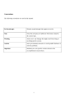
used in this manual: Screen messages Note Warning Caution Important Denotes actual messages that appear on screen Gives bits and pieces of additional information related to the current topic. Alerts you to any damage that might result from doing or not doing specific actions. Gives precautionary - Acer AL2423W | AL2423W LCD Monitor - Page 4
in the printed Service Guide, for ACER-AUTHORIZED SERVICE PROVIDERS, your Acer office may have a DIFFERENT part number code to those given in the FRU list of this printed Service Guide. You MUST use the list provided by your regional Acer office to order FRU parts for repair and service of customer - Acer AL2423W | AL2423W LCD Monitor - Page 5
B digital device, pursuant to Part 15 of the FCC Rules. accordance with the instructions, may cause harmful 2. Shielded interface cables and AC power cord, if any, must be monitor to rain or moisture. Dangerously high voltages are present inside the monitor. Do not open the cabinet. Refer servicing - Acer AL2423W | AL2423W LCD Monitor - Page 6
power strips and extension cords. Overloading can result in fire or electric shock. l Never push any object into the slot on the monitor cabinet. It could short circuit parts causing a fire or electric shock. Never spill liquids on the monitor. l Do not attempt to service the monitor yourself - Acer AL2423W | AL2423W LCD Monitor - Page 7
The following symptoms are normal with LCD monitor and do not indicate a problem. NOTES l Due to the nature of the fluorescent light, the screen may flicker during initial use. Turn off the Power Switch and then turn it on again to make sure the flicker disappears. l You may find slightly uneven - Acer AL2423W | AL2423W LCD Monitor - Page 8
Table of contents Chapter 1 MONITOR FEATURE 9 Chapter 2 OPERATING INSTRUTION 21 Chapter 3 MACHINE ASSEMBLY 28 Chapter 4 TROUBLE SHOOTING 40 Chapter 5 CONNECTOR INFORMATION 43 Chapter 6 FRU LIST 45 Chapter 7 SCHEMATIC DIAGRAM 49 Chapter 8 POWER BOARD INFORMATION 53 - 8 - - Acer AL2423W | AL2423W LCD Monitor - Page 9
Monitor Feature Chapter 1 LCD Panel Input Display Color Maximum Dot Clock ® Max Resolution Plug & Play EPA ENERGY STAY Audio output Input Connector Input Video Signal Screen Size (Active) Power Source Environmental Considerations Driving system TFT Color LCD Size 24" wide Pixel pitch 0.270mm - Acer AL2423W | AL2423W LCD Monitor - Page 10
Compliance 7.0 kg / 10.7 kg 572 x 454.1 x 296.2 mm (with stand) 8.5kg/12kg(OnlyAL2423Wh/AL2423Wr) 572 x 425.5 x 296.2 mm (with stand)(Only AL2423Wh/AL2423Wr) * Power Switch * MENU / EXIT * < / Volume * > / Volume * AUTO / ENTER * Contrast/brightness * Focus * Clock * H.Position * W.Position - Acer AL2423W | AL2423W LCD Monitor - Page 11
memory modes in total. 26 modes are preset and 8 modes are user definable. MODE NO. RESOLUTION 1 720 x 400 2 640 x 480 3 640x480 4 640 x 480 Dot clock(MHz) 28.321 25.175 30.24 31.5 f h H-Total ( us ) H-Sync ( us ) H-B-P ( us ) H-Active ( us ) H-F-P ( us ) 31.469kHz 31.78(900dots) 3.813 - Acer AL2423W | AL2423W LCD Monitor - Page 12
(3 lines) 0.448 (21 lines) 12.80 (600lines) 0.021 (1 line ) + / + Y MODE NO. RESOLUTION 9 800 x 600 10 832 x 624 11 1024 x 768 12 1024 x 768 Dot clock(MHz) 50 57.283 32 dots ) 0.369(24 dots) 56.48kHz 17.71(1328 dots) 1.81(136 dots) 1.92(144 dots) 13.65(1024 dots) 0.32(24 dots) f v 72Hz - Acer AL2423W | AL2423W LCD Monitor - Page 13
lines) 12.800(864 lines) V-F-P ( ms ) 0.02 (1 lines) 0.016 (1 line ) 0.013 (1 lines) 0.015(1 lines) SYNC. H/V +/+ +/+ +/+ +/+ POLARITY SEP . SYNC Y Y Y Y MODE NO. RESOLUTION 17 1280 x 960 18 1600 x 1200 19 1280 x 720 20 1280 x 768 Dot clock(MHz) 108 162 74.176 79.5 f h 60 - Acer AL2423W | AL2423W LCD Monitor - Page 14
ms ) SYNC. H/V POLARITY SEP . SYNC 0.017 ( 1 line ) + / + Y 0.013 ( 1 line ) + / + Y MODE NO. RESOLUTION 21 1280 x 768 22 1360 x 768 0.111 (5 lines) + / + HDTV 23 1440 x 900 0.063 (3 lines) -/+ Y 24 1440 x 900 Dot clock(MHz) 102.25 85.5 106.5 136.75 f h 60.289KHz 47.712KHz 55.935KHz - Acer AL2423W | AL2423W LCD Monitor - Page 15
) 15.474 (480 lines ) V-F-P ( ms ) SYNC. H/V POLARITY SEP . SYNC 0.046 ( 3 line ) 0.193 (6 lines ) -/+ + / + Y Y A : H-Total O : V-Total B : H- Sync P : V- Sync width width C : H- Back Q :.V- Back porch porch D : H- Video R : V- Video width width E : H- Front S :.V- Front porch porch - 15 - - Acer AL2423W | AL2423W LCD Monitor - Page 16
Monitor Block Diagram 5 Page 4 4 03. Graphic Inputs 3 Page 5 2 PWM0 PWM1 PBIAS PWM0 PWM1 PBIAS PWM0 PWM1 C C Power SVDATA[0..7] SHS SVODD SVS SVCLK SVDV Page 6 MSTR_SDA Top Level Size Date: Document Number SCHEMATIC1 Saturday, December 24, 2005 WDTB Sheet 7 Rev C2A of 8 5 4 3 2 - Acer AL2423W | AL2423W LCD Monitor - Page 17
PCB CONDUCTOR VIEW Main Board - 17 - - Acer AL2423W | AL2423W LCD Monitor - Page 18
- 18 - - Acer AL2423W | AL2423W LCD Monitor - Page 19
Power Board - 19- - Acer AL2423W | AL2423W LCD Monitor - Page 20
Button board - 20 - - Acer AL2423W | AL2423W LCD Monitor - Page 21
OPERATING INSTRUCTIONS Chapter 2 Front Panel Definition This Section defines the front panel User Interface for Led Indictor and Key function. Key Definition: There to view the OSD. Press again to enter a selection in the OSD. Power on/off 5 Power Green: power on Orange: in sleep mode - 21 - - Acer AL2423W | AL2423W LCD Monitor - Page 22
OSD menu Contrast: This adjusts dark and light shades of color relative to each other. Brightness: This adjusts the brightness of the picture on the screen. Focus: This removes any horizontal distortion and makes the picture clear and sharp. Clock: If there are any vertical stripes seen on the - Acer AL2423W | AL2423W LCD Monitor - Page 23
: Select the OSD menu language. Select from English, German, Spanish, Russia, Nederlands, French, Italian, and Finnish. OSD Settings: This changes the position of the OSD window on the screen and the staying time. Input signal: Select either Analog Input or Digital Input video. - Acer AL2423W | AL2423W LCD Monitor - Page 24
Information: This shows information about the screen. Reset: Resets all settings to default levels. Exit: Exit from OSD. - Acer AL2423W | AL2423W LCD Monitor - Page 25
Factory Mode You can entry into factory mode when press "Auto" and then press"Power" Key(LED light),it is successful if Power LED Light is amber. Factory1 Adjustment Reset: Resets all settings to default levels. Factory2 Adjustment This page only visible in factory mode AUTO BURN : Use - Acer AL2423W | AL2423W LCD Monitor - Page 26
system status and defined as bellows : LED Color Green System Status System in normal operation mode Amber System in power-saving mode Dark System in power-off mode LOGO : When the monitor is power on, the LOGO will be showed in the center, and disappear slowly. HOW TO OPTIMIZE THE DOS-MODE - Acer AL2423W | AL2423W LCD Monitor - Page 27
automatically switch to an OFF mode. This reduces the monitor's internal power supply consumption. After the video input signal is restored, full power is restored and the display is automatically redrawn. The appearance is similar to a "Screen Saver" feature except the display is completely off - Acer AL2423W | AL2423W LCD Monitor - Page 28
how to assemble the monitor for maintenance and trouble shooting NOTE : 1. The screws for the different components vary in size. During the disassembly process, group the screws with the corresponding to avoid mismatch when putting back the components. 2. Note : The monitor surface is susceptible to - Acer AL2423W | AL2423W LCD Monitor - Page 29
Real View : Top View : - 29 - - Acer AL2423W | AL2423W LCD Monitor - Page 30
Side View : ( unit : mm ) - 30 - - Acer AL2423W | AL2423W LCD Monitor - Page 31
1. [GET PCB SHIELD AND PUT IT IN THE MIDDLE OF CONVEYER] 1 1. [GETM/B ANDM/B CABLE AND PUT ON TOOL ,THEN INSERT INV CABLE ININVERTER/B CONNECTOR. ] 1. GET POWER/B AND INSERT JUMPER IN THE APPOINTED PLACE OF JP10 1 AT 2. [LOCK 3PCS SCREW ON SHIELD] 2-3 2-1 2- 2 - 31 - - Acer AL2423W | AL2423W LCD Monitor - Page 32
SCREW(M4.0*8-B) IN 2 INV/B] 3. [GET INV MODULE AND PUT ON LINE] 3 1 3 1-2 2-3 2 1.[GET INVETOR SUPPORN AND INSERT INV MODULE] 2.[STICK MYLAR 1PCS ON THE POWER/B AS PICTURE SHOWS] 3.[GET CABEL INV/B AND INSERT INV MLDULE ] 1. [GET 2PCS BKT-E AND ASSY WITH INV MODULE] 2. [FASTEN 4*PCS SCREW(M4 - Acer AL2423W | AL2423W LCD Monitor - Page 33
1 2 1-2 1-1 2 2 2 3-3 3-2 3-11 1. [TEAR OFF THE INCOMING TAPE] 2. [GET PANEL AND PUT IT ON THE CONVEYER] 1. [STICK CODE*1PCS ON THE APPOINTED PLACE OF PANEL] 2. GET TRAVEL CARD AND SCAN IT AND PANEL CODE] 3. [INSERT CCFT CABEL IN INV MODULE ] - 33 - - Acer AL2423W | AL2423W LCD Monitor - Page 34
CARD, TEAR OFF 1-3 1*PCS S/N FROM TRAVEL CARD AND PASTE IT ON THE PANEL 1-4 BACK,THEN SCAN S/N AND PANEL CODE 2. GET LEFT BKT AND LOCK 2*PCS SCREW(M3*5-I) TO FASTEN IT AND 2-1 PANEL 1. [GET POWER /MYLAR AND STICK 1 SHIELD] 2. [LOCK 3*PCS M3*4-I IN BEZEL] 2-2 2-1 3. [GET 1PCS WIRE - Acer AL2423W | AL2423W LCD Monitor - Page 35
1 [LOCK 3*PCS M3*4-I IN BEZEL] 1-3 1-2 1-1 2. [INSERT LVDS CABEL IN LCD ANNECTENT] 3. [GET SHIELD AND PUT ON MONITOR] 3 1 2-3 2-3 1. [STICK YELLOW TEYE ON THE LCD ANNECTENT ] 2. [LOCK 4PCS SCREW FIXING SHIELD IN BKT] 2-3 2-3 1-1 2-2 1. [GET PANEL-HOOKON AND ASSY MONITOR BOSS] 2-3 - 35 - - Acer AL2423W | AL2423W LCD Monitor - Page 36
1. [LOCK 4PCS(F3*10-B)SCREW FIXING PANEL-HOOKON MONITOR ] 1 1-1 1-3 1-2 1. [GET THE SPEAK ASSY WITH BEZEL BOSS AND INSERT CABLE SPEAK] 2. [GET BUTTON/B AND CABLE BUTTON THAN INSERT IN BUTTON ANNECTENT] 1-4 1-3 1-2 1-1 1. [LOCK 4PCS (F2.5*8-P)SCREW FIXING SPEAK ASSY] 2. [ASSY BUTTON /B WITH - Acer AL2423W | AL2423W LCD Monitor - Page 37
1-4 1-3 1-2 1-1 2 1. [LOCK 4PCS I/O NUT SCREW VGA ANNECTENT] 2. [CLEAN UP THE CABLE] 1. [GET 2PCS AL FILM AND STICK BKT ] 1 2. [GET 1PCS AL FILM AND STICK ON THE SHIELD] 1-2 12 2 2 1. GET LCD COVER AND INSPECT ITS APPEARANCE 2. ASSEMBLE LCD COVER TO BEZEL - 37 - - Acer AL2423W | AL2423W LCD Monitor - Page 38
AT THE APPOINTED PLACE 1. FETCH TRAVEL CARD, TEAR OFF 1*PCS APPOINTED S/N FROM TRAVEL CARD AND PASTE IT ON 1 THE COVER 2-2 2-1 2. LOCK 2*PCS SCREW (F3*8-B) TO FASTEN BEZEL AND LCD COVER 3. GET STAND NECK AND INSPECT IF IT IS DIRTY AND SCRATCHED,THEN 3 PUT IT IN THE CONVEYER 1.LOCK 4*PCS - Acer AL2423W | AL2423W LCD Monitor - Page 39
INSERT VGA CABLE INTO VGA CONNECTOR AND INSERT POWER CORD INTO POWER CONNECTOR 2 2. GET BASE FIXTRUE AND ASSEMBLE IT TO STAND NECK. 12 1. INSERT DVI CABLE INTO DVI CONNECTOR AND INSERT POWER CORD INTO POWER CONNECTOR 2. STAND UP THE MONITOR AND STICK TRAVALCARD AT LEFT DOWNSIDE OF MONITOR - 39 - - Acer AL2423W | AL2423W LCD Monitor - Page 40
1. No Power No Power Chapter 4 Change NO Power Board No Check Short Of Main Board NO Change U13,U12 NO Change X1 or U4 NO Change U7 or Change U7 RUN Software ISP Yes Check CN7 +12V and +5V Yes - Acer AL2423W | AL2423W LCD Monitor - Page 41
2. Missing Color Change NO Cable Change NO R4,R8,R10,U 7 NO Change U7 or CN5 Cable or Panel NO Adjustment R/G/B Color Missing Color Check VGA or DVI Cable Yes Check R4,R8,R10 Yes Check CN5 LVDS Signal Yes Check OSD R/G/B Gain Yes Change Panel - 41 - - Acer AL2423W | AL2423W LCD Monitor - Page 42
3. Always show "NO SIGNEL" "NO SIGNEL" Change NO Cable Check VGA or DVI Cable Yes VGA Check R4,R8,R10,R20, R21 Yes Yes Change U7 DVI Check U7 Pin 109, 110, 112,113, 117, 118, 120, 121 NO Change VGA Cable or R4, R8,R10, R20, R21 or U7 NO Change DVI Cable or U7 - 42 - - Acer AL2423W | AL2423W LCD Monitor - Page 43
Connector Information Phonejack stereo PIN1. AC power cord : CEE22 typed connector PIN2. Audio cable PIN3. Audio : Line-in receptacle Chapter 5 The PIN assignment of the 15 pin mini D-SUB connector / cable is as follows: PIN Signal 1 Red 2 Green 3 Blue 4 No Pin 5 Ground 6 Ground Red 7 Ground - Acer AL2423W | AL2423W LCD Monitor - Page 44
The PIN assignment of the 24 pin DVI-D connector / cable is as follows: PIN Signal PIN Signal 1 TMDS data22 TMDS data2+ 3 TMDS data2 shield 4 NC 5 NC 6 DDC clock 7 DDC data 8 Not connected 9 TMDS data110 TMDS data1+ 12 NC PIN Signal 13 NC 14 +5V 15 Ground (return for +5 V and H/V sync) 16 Hot plug - Acer AL2423W | AL2423W LCD Monitor - Page 45
printed Service Guide. For ACER-AUTHORIZED CERVICE PROVIDERS, your Acer office may have a DIFFERENT part number code to those given in the FRU list of this printed Service Guide. You MUST use the local FRU list provided by your regional Acer office to order FRU parts repair and service of customer - Acer AL2423W | AL2423W LCD Monitor - Page 46
- Acer AL2423W | AL2423W LCD Monitor - Page 47
PART NUMBER PART PART NUMBER PART DESCRIPTION NUIT 1 22 FBWDTB06015 PANEL HOOK WDTB GP 2 1 23 MF30100B008 SCREW F3.0*10.0-B BLACK GP 4 1 24 EBWDTB01013 INVERTOR SUPORT WDTB GP 1 1 25 FCWDTB03017 POWER 31 EBL9TB02013 HINGE COVER L9TB GP 1 BLACK NI)GP 2 4 39 MM4.100B244 SCREW M4.0*10-B BLACK - Acer AL2423W | AL2423W LCD Monitor - Page 48
Part list Above picture show the description of the following component Item Picture Description Part No 1 back cover 25WDTBLC001 2 bezel 34WDTBLB004 3 base 38WDTBBS006 4 stand 37WDTBSU007 5 screw MM40080BBW1 - 48 - - Acer AL2423W | AL2423W LCD Monitor - Page 49
Chapter 7 SCHEMATIC DIAGRAM Main Board Circuit 5 4 3 Change 5V to 3.3V +12V L9 1 2 D19 C A +18V +3.3_DVDD 100R 100R 100R GPIO24/MENU GPIO25/SEL GPIO26/POWER GPIO27/DOWN GPIO28/UP GPIO29/RIGHT LEFT/LED_G GPIO24/MENU GPIO25/SEL GPIO26/POWER GPIO27/DOWN GPIO28/UP GPIO29/RIGHT GND 10 - Acer AL2423W | AL2423W LCD Monitor - Page 50
3 3 1 2 1 2 D 3904 SI2301 Component top view Component top view 09/23 FIX +3.3_SDRAM MPWR R123 R125 0R 0R/NC C111 47uF/25V/NC R126 4K7/NC Q1 SI2301DS/ 8 9 10 11 12 13 14 15 16 17 18 19 20 21 22 23 24 TXOC+ R144 TXO3+ R147 TXE0+ R149 TXE1+ TXE2+ TXEC+ TXE3+ R155 R157 R159 - Acer AL2423W | AL2423W LCD Monitor - Page 51
L1206 OCM 20 bit ADD mode In ckt debug on DDC_CH2 Int OSC OCM 24 bit ADD mode In ckt debug on DDC_CH1 Ext OSC S_CLK S_CSn Lo Normal /MENU GPIO25/SEL GPIO26/POWER GPIO27/DOWN GPIO28/UP GPIO29/RIGHT GPIO30/LEFT/LED_G GPIO31/KEYPAD GPIO24/MENU GPIO25/SEL GPIO26/POWER GPIO27/DOWN GPIO28/UP GPIO29 - Acer AL2423W | AL2423W LCD Monitor - Page 52
NC GND RX0RX0+ GND RX5RX5+ GND RXC+ RXC- 17 18 19 20 21 22 23 24 R34 10R 1% R35 10R 1% R36 10R 1% R37 10R 1% RX0RX0+ RXC+ RXC- R38 RED GRN BLU HS GND C1 C2 C3 C4 C5 26 RED_IN GREEN_IN BLUE_IN HS B DVI-I GND GND 1 1 1 1 +3.3_AVDD D10 D11 D12 D13 3 DAN217K/NC 3 DAN217K/ - Acer AL2423W | AL2423W LCD Monitor - Page 53
Power Board Current set Information Power Board AS05B560004 Chapter 8 P/N Model Name Lamp Curren AS05B560004 AAM240M2006 Samsung LTM240M2-L02 (VA) 6mA NO Jump - 53-
-
 1
1 -
 2
2 -
 3
3 -
 4
4 -
 5
5 -
 6
6 -
 7
7 -
8
-
9
-
10
-
11
-
12
-
13
-
14
-
15
-
16
-
17
-
18
-
19
-
20
-
21
-
22
-
23
-
24
-
25
-
26
-
27
-
28
-
29
-
30
-
31
-
32
-
33
-
34
-
35
-
36
-
37
-
38
-
39
-
40
-
41
-
42
-
43
-
44
-
45
-
46
-
47
-
48
-
49
-
50
-
51
-
52
-
53
 |
 |
- 1 -
Acer AL2423 W
Service Guide
Service guide files and updates are available on the CSD web: for more
information,
Please refer to
100% Recycled Paper