Acer Altos G310 MK2 User Manual
Acer Altos G310 MK2 Manual
 |
View all Acer Altos G310 MK2 manuals
Add to My Manuals
Save this manual to your list of manuals |
Acer Altos G310 MK2 manual content summary:
- Acer Altos G310 MK2 | User Manual - Page 1
Acer Altos G310 Mk2 series - Acer Altos G310 MK2 | User Manual - Page 2
Reserved. Acer Altos G310 Mk2 series User's Guide 1st Issue: February 2005 Changes may be made periodically to the information in this publication without obligation to notify any person of such revisions or changes. Such changes will be incorporated in new editions of this manual or supplementary - Acer Altos G310 MK2 | User Manual - Page 3
installation. This device generates, uses, and can radiate radio frequency energy, and if not installed and used in accordance with the instructions, may cause harmful interference to radio communications. However, there is no guarantee that interference will not occur in a particular installation - Acer Altos G310 MK2 | User Manual - Page 4
, which is granted by the Federal Communications Commission, to operate this server. Use conditions This part complies with Part 15 of the FCC Rules Equipment Regulations. Laser compliance statement The CD-ROM drive in this server is a laser product. The CD-ROM drive's classification label (shown - Acer Altos G310 MK2 | User Manual - Page 5
safety instructions Read these instructions carefully. Save these instructions for future reference. 1 Follow all warnings and instructions marked on all servicing to qualified service personnel. 11 Unplug this product from the wall outlet and refer servicing to qualified service personnel under - Acer Altos G310 MK2 | User Manual - Page 6
when the operating instructions are followed. Adjust only those controls that are covered by the operating instructions since improper If the product exhibits a distinct change in performance, indicating a need for service. 12 Replace the battery with the same type as the product's battery we - Acer Altos G310 MK2 | User Manual - Page 7
statement iv Important safety instructions v 1 System information 1 Product briefing 3 Processor 3 Memory subsystem 3 Storage 4 Graphics interface 4 Networking 4 I/O ports 4 Serial ATA ports 4 PCI I/O 4 Caring features 5 Product specification summary 7 2 System tour - Acer Altos G310 MK2 | User Manual - Page 8
precautions 29 Preinstallation instructions 30 Post-installation instructions 30 Opening the server 31 Before opening the server 31 To remove 40 Upgrading the system memory 41 Memory configuration 41 To remove a DIMM 43 To install a DIMM 44 Reconfiguring the system memory 44 - Acer Altos G310 MK2 | User Manual - Page 9
6 Troubleshooting 79 Troubleshooting 81 Resetting the system 81 Problems following initial system installation 82 First steps checklist 82 Hardware diagnostic testing 83 Verifying proper operation of key system lights 84 Confirming loading of the operating system 84 Specific problems - Acer Altos G310 MK2 | User Manual - Page 10
Beep Codes 95 BIOS Error Messages 95 Appendix A: Embedded SATA RAID Technology for the Altos G310 Mk2 99 SATA ports 101 BIOS Features 101 Driver Features 102 Manageability/Disk console 102 Configuring arrays 104 Configuration strategies 104 Assigning RAID levels 104 Performing - Acer Altos G310 MK2 | User Manual - Page 11
Create RAID1 volume 121 Assign hot spare disk 122 Initialize RAID volume 122 Save and exit MegaRAID configuration utility 122 - Acer Altos G310 MK2 | User Manual - Page 12
Contents - Acer Altos G310 MK2 | User Manual - Page 13
1 System information - Acer Altos G310 MK2 | User Manual - Page 14
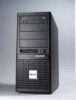
The Acer Altos G310 Mk2 server is an entry level single-processor general purpose system. The system offers a new standard for flexible productivity ideal for small business or workgroup applications. - Acer Altos G310 MK2 | User Manual - Page 15
channel support • Maximum upgrade - 4 GB • Two-way interleaving support Warning! Functionality issues may be encountered if mixed memory types are installed on the same server board. DIMM modules of identical type, banking and stacking technology, and vendor should be installed in the Altos G310 Mk2 - Acer Altos G310 MK2 | User Manual - Page 16
• Two USB 2.0 ports • Rear • Four USB 2.0 ports • Two PS/2 ports (keyboard/mouse) • Two LAN ports (RJ-45) • One parallel port • One serial port • One VGA port Serial ATA ports • Four Serial ATA ports supporting RAID 0 or RAID 1 PCI I/O • Six PCI slots • Three 32-bit/33 MHz PCI slots • Two x4 PCI - Acer Altos G310 MK2 | User Manual - Page 17
5 Caring features Part of Acer's mission, as a company that cares about its end users, is to provide features that make operation, maintenance, and upgrading your system simpler and faster. The Altos G310 Mk2 is no exception to this rule. The following features and options are provided. • Cost - Acer Altos G310 MK2 | User Manual - Page 18
6 1 System information - Acer Altos G310 MK2 | User Manual - Page 19
7 Product specification summary Highlighted below are the system's key features: • Single Intel® Pentium® 4 processor supporting Hyper-Threading technology and EM64T • 533/800 MHz FSB supports processor speeds from 2.8 GHz to 3.8 GHz or higher • Intel® 7221 Chipset • Intel® E7221MC Memory - Acer Altos G310 MK2 | User Manual - Page 20
8 • Operating Systems supported • Microsoft® Windows® Server 2003 • Red Hat® Enterprise Linux 3.0 • Novell Netware 6.5 1 System information - Acer Altos G310 MK2 | User Manual - Page 21
2 System tour - Acer Altos G310 MK2 | User Manual - Page 22
This chapter provides locations of various components and ports, and instructions on how to set up the system. Procedures on how to connect peripherals are also explained. - Acer Altos G310 MK2 | User Manual - Page 23
U W PCI 32-bit/33 MHz slot 3 Rear fan connector PCI Express x4 (w/ x1 throughout) slot 2 PCI Express x4 (w/ x1 throughout) slot 1 Intel 82551QM LAN controller PCI 32-bit/33 MHz slot 2 PCI 32-bit/33 MHz slot 1 Marvell 88E8050 PCI Express Gigabit Ethernet Controller PCI Express x8 slot 1 Back - Acer Altos G310 MK2 | User Manual - Page 24
1 (Black) Socket I/O controller Floppy disk drive connector Two x12 Power connector Parallel ATA IDE connector CMOS battery Chassis intrusion connector BIOS configuration jumper Clear CMOS jumper Front fan connector Serial ATA connectors Front panel USB connectors Serial B connector SCSI status LED - Acer Altos G310 MK2 | User Manual - Page 25
setting 1-2 Configure Recovery 2-3 1 None 1 Function/Mode Normal Jumper Setting 1-2 1 Clear CMOS 2-3 1 No Jumper None 1 Configuration OM16682 The BIOS uses current configuration information and passwords for booting. After the POST runs, Setup runs 3 automatically. The maintenance menu - Acer Altos G310 MK2 | User Manual - Page 26
14 2 System tour External and internal structure Front bezel Note: One pair of system keys are provided (attached to the rear panel of the system). No. Description 1 CD-ROM drive 2 CD-ROM headphone port 3 CD-ROM volume control 4 CD-ROM activity indicator - Acer Altos G310 MK2 | User Manual - Page 27
15 No. Description 5 FDD eject button 6 FDD (floppy disk drive) 7 FDD activity indicator 8 Security keylock 9 HDD activity indicator 10 System power indicator 11 System power button 12 USB 2.0 ports (two) 13 5.25-inch device bays 14 CD-ROM stop/eject button - Acer Altos G310 MK2 | User Manual - Page 28
16 Front panel 2 System tour No. Description 1 CD-ROM drive 2 CD-ROM headphone port 3 CD-ROM volume control 4 CD-ROM activity indicator 5 FDD eject button 6 FDD (floppy disk drive) 7 FDD activity indicator 8 Security keylock - Acer Altos G310 MK2 | User Manual - Page 29
17 No. Description 9 HDD activity indicator 10 System power indicator 11 System power button 12 USB 2.0 ports (two) 13 5.25-inch device bays 14 CD-ROM stop/eject button - Acer Altos G310 MK2 | User Manual - Page 30
18 Rear panel 2 System tour No. Icon 1 2 3 4 5 6 Description Main power supply unit PS/2 mouse port PS/2 keyboard port Parallel/printer port Serial port VGA port - Acer Altos G310 MK2 | User Manual - Page 31
19 No. Icon 7 8 Description USB 2.0 ports (four) LAN ports 9 Side panel tool-less screws (bottom) 10 System ventilation/fan exhaust 11 Main power supply fan-exhaust 12 Side panel tool-less screws (top) - Acer Altos G310 MK2 | User Manual - Page 32
20 Internal components 2 System tour No. Description 1 Power supply unit 2 System fan 3 Mainboard 4 PCI slots 5 HDD bays 6 3.5" device bays 7 5.25" device bays - Acer Altos G310 MK2 | User Manual - Page 33
3 Getting Started - Acer Altos G310 MK2 | User Manual - Page 34
This chapter gives information on setting up and starting to use your system - Acer Altos G310 MK2 | User Manual - Page 35
as air conditioners, radio and TV transmitters, etc. Checking the package contents Check the following items from the package: • Acer Altos G310 Mk2 series system • Acer Altos G310 Mk2 series accessory box • System keys (attached to the rear panel of the system) If any of the above items are damaged - Acer Altos G310 MK2 | User Manual - Page 36
the system. To power on the system, press the power button on the front panel. The system starts up and displays a welcome message. After that, a series of power-on self-test (POST) messages appears. The POST messages indicate if the system is running well or not. Note: If the system does - Acer Altos G310 MK2 | User Manual - Page 37
You can then turn off all peripherals connected to your server. If you are unable to shutdown the server within Windows, press and hold the power button for at least four seconds to force quit all applications and shut down. Power-on problems If the system does not boot after you have applied power - Acer Altos G310 MK2 | User Manual - Page 38
26 3 Getting Started - Acer Altos G310 MK2 | User Manual - Page 39
4 Configuring the system - Acer Altos G310 MK2 | User Manual - Page 40
This chapter discusses the precautionary measures and installation procedures you need to know when upgrading the system. - Acer Altos G310 MK2 | User Manual - Page 41
of the server are upgradeable such as the drives, the CPU, the memory, and the expansion cards. However, for safety purposes, we do not recommend that you perform these upgrades yourself. If you want to replace or upgrade any of these components, contact your dealer or a qualified service technician - Acer Altos G310 MK2 | User Manual - Page 42
sections for specific installation instructions on the component you want to install. Warning! Failure to properly turn off the server before you unless you are a qualified service technician. Post-installation instructions Observe the following after installing a server component: 1 See to it - Acer Altos G310 MK2 | User Manual - Page 43
opening the server Before opening the server, observe the following precautions: 1 Turn off the system and all the peripherals connected to it. 2 Unplug all cables from the power outlets. 3 Place the system unit on a flat, stable surface. Note: Because of the G310 Mk2 design specification, only the - Acer Altos G310 MK2 | User Manual - Page 44
32 4 Configuring the system To remove the side panel The side panel is attached to the server by two (non-removable) thumbscrews. To remove the side panel: 1 Locate the System Keys (if necessary) and unlock the system lock on the front panel. 2 - Acer Altos G310 MK2 | User Manual - Page 45
the chassis (1). 2 Gently pull the bottom of the front bezel away from the chassis (2), lift it to approximately 45 degrees, then detach the top and move it away from the chassis. - Acer Altos G310 MK2 | User Manual - Page 46
34 4 Configuring the system Installing and removing storage devices The system supports 3.5-inch and 5.25-inch internal storage devices. The system comes pre-installed with a floppy drive and a CD-ROM drive. The empty 5.25-inch half-height - Acer Altos G310 MK2 | User Manual - Page 47
drive bay until it locks into place with an audible "click." 6 Connect the power and IDE cables to the new drive. 7 Observe the post-installation instructions described on page 30. - Acer Altos G310 MK2 | User Manual - Page 48
instructions for removing and installing a CPU. Caution: Processor must be appropriate. You may damage the server board if you install a processor that is inappropriate for your server charge while handling the processor. (2) Avoid moving around unnecessarily. To install the Processor Caution: - Acer Altos G310 MK2 | User Manual - Page 49
37 2 Lift the load plate. Do not touch the socket contacts. 3 Remove the protective socket cover from the load plate. Do not discard the protective socket cover. Always replace the socket cover if the processor is removed from the socket. 4 Remove the processor from the protective processor cover. - Acer Altos G310 MK2 | User Manual - Page 50
38 4 Configuring the system 5 Hold the processor with your thumb and index fingers oriented as shown below. Make sure fingers align to the socket cutouts. Align notches with the socket. Lower the processor straight down without tilting or sliding the processor in the socket. 6 Pressing down on - Acer Altos G310 MK2 | User Manual - Page 51
39 To install the processor fan heat sink The Altos G310 Mk2's server board has an integrated processor fan heat sink retention mechanism (RM). Connecting the processor fan heat sink cable Connect the processor fan heat sink cable to the 4-pin processor fan header. - Acer Altos G310 MK2 | User Manual - Page 52
Turn off all peripheral devices connected to the server. Turn off the server. 3 Remove the AC power cord from the server. 4 Remove the server's cover. See the documentation that accompanied your server chassis for instructions on removing the server's cover. 5 Unplug the processor fan cable from the - Acer Altos G310 MK2 | User Manual - Page 53
41 Upgrading the system memory Memory configuration This section includes instructions for removing and installing a memory module. The memory modules are located on the main server board as shown below: Channel A DIMM 0 DIMM 1 Channel B DIMM 0 DIMM 1 The two tables (below) summarize the - Acer Altos G310 MK2 | User Manual - Page 54
42 4 Configuring the system Warning! Functionality issues may be encountered if mixed memory types are installed on the same server board. DIMM modules of identical type, banking and stacking technology, and vendor should be installed in the Altos G310 Mk2. - Acer Altos G310 MK2 | User Manual - Page 55
43 To remove a DIMM Before installing a new DIMM in a socket, remove first any previously installed DIMM from that socket. Important: Before removing any DIMM from the mainboard, make sure to create a backup file of all important data. 1 Observe the precautions and pre-installation procedures - Acer Altos G310 MK2 | User Manual - Page 56
have inserted it incorrectly. Reverse the orientation of the DIMM and insert it again. 6 Observe the "Post-installation instructions" on page 30. Reconfiguring the system memory The system automatically detects the amount of memory installed. Run the BIOS setup to view the new value for total system - Acer Altos G310 MK2 | User Manual - Page 57
or PCI Express cards. Note: The BIOS setup automatically detects and assigns resources to the new device (applicable only to Plug-and-Play expansion cards). To install an expansion card Note: The illustrations used in this section show the Altos G310 Mk2 server chassis. 1 Observe the ESD precautions - Acer Altos G310 MK2 | User Manual - Page 58
the card is properly seated. 9 Secure the card with the tool-less bracket card lock removed in step three above (4). 10 Observe the "Post-installation instructions" on page 30. - Acer Altos G310 MK2 | User Manual - Page 59
47 Installing and removing a hard disk Although the Altos G310 Mk2 has four hard disk slots, the system board only supports a maximum of three. To remove a hard disk Follow these steps to replace your computer's hard disk: 1 Remove the side and front panels (see page 32 - Acer Altos G310 MK2 | User Manual - Page 60
48 4 Configuring the system 1 Remove the side panel (see page 32). 2 Attach the HDD rails to the sides of the drive housing as shown below. 3 Insert the drive into an empty HDD slot (slot 1 or slot 3) until it locks into place with an audible "click" (1). 4 Attach the power and IDE cables to the - Acer Altos G310 MK2 | User Manual - Page 61
5 BIOS setup - Acer Altos G310 MK2 | User Manual - Page 62
This chapter gives information about the system BIOS and discusses how to configure the system by changing the settings of the BIOS parameters. - Acer Altos G310 MK2 | User Manual - Page 63
• When changing the password or making other changes to the security setup BIOS setup loads the configuration values in a battery-backed nonvolatile memory called CMOS RAM. This memory area is not part of the system RAM which allows configuration data to be retained when power is turned off. Before - Acer Altos G310 MK2 | User Manual - Page 64
the six major BIOS menus: • Main • Advanced • Security • Power • Boot • Exit The parameters on the screens shown in this User's Guide display default system system. Note the following reminders when moving around the setup screen: • Use the Left and Right arrow keys to move to the next page or to - Acer Altos G310 MK2 | User Manual - Page 65
that a submenu screen is available. • Press F1 for General Help on using the BIOS setup. • Press F9 to set up defaults • Press F10 to save changes and close the BIOS setup. • Press Esc to close the BIOS setup. In the descriptive table following each of the screen illustrations, settings in boldface - Acer Altos G310 MK2 | User Manual - Page 66
54 5 BIOS setup Main The Main menu displays basic and important information about the system. This information is necessary for troubleshooting and may be required when asking for technical support. The last parameter on the screen lets you define the system's time and date settings. The real- - Acer Altos G310 MK2 | User Manual - Page 67
any incorrect value may cause the system to malfunction. Press Enter to enter the submenu screen of the parameters shown in the screen below BIOS SETUP UTILITY Main Advanced Security Power Boot Exit Setup Warning: Setting items on this screen to incorrect values may cause the system to malfunction - Acer Altos G310 MK2 | User Manual - Page 68
Advanced PCI Configuration PCI Slot1 IRQ Priority PCI Slot2 IRQ Priority PCI Slot3 IRQ Priority BIOS SETUP UTILITY [Auto] [Auto] [Auto] Manual IRQ selection does not guarantee PCI slot device will be configured with choice because PnP ISA cards ( If present ) are assigned the available resources - Acer Altos G310 MK2 | User Manual - Page 69
Play O/S Numlock Max CPUID Value Limit: BIOS SETUP UTILITY [No] [On] [Disabled] No, lets the BIOS configure all the devices in the system. Exit ESC Exit Parameter Plug and Play OS Description Selects OS that supports PnP features Numlock Selects power-on state for Numlock Max CPUID Value - Acer Altos G310 MK2 | User Manual - Page 70
setup Advanced Peripheral Configuration Serial Port A Serial Port B Parallel Port Mode Onboard Gb LAN Onboard 10/100 LAN ASF Support BIOS SETUP UTILITY [Auto] [Auto] [Auto]] [Bi-directional] [Enabled] [Enabled] [Enabled] ←→ Select Screen ↑↓ Select Item Enter Select ? Sub-Menu Tab Select Field - Acer Altos G310 MK2 | User Manual - Page 71
EPP ECP Onboard Gb LAN Sets onboard Gb LAN Enabled Disabled Onboard 10/ 100 LAN Sets onboard 10/100 LAN Enabled Disabled ASF Support Sets ASF support Enabled Disabled Drive Configuration Advanced Drive Configuration ATA/IDE Configuration Intel(R) RAID Technology SATA AHCI Mode - Acer Altos G310 MK2 | User Manual - Page 72
5 BIOS setup Parameter Description Option ATA/IDE Configuration Disabled: All IDE resources disabled. LEGACY: Up to 2 IDE channels enabled for OS requiring legacy IDE operation. ENHANCED: All SATA and PATA resources enabled Disabled Legacy Enhanced Intel RAID Technology Sets RAID function - Acer Altos G310 MK2 | User Manual - Page 73
61 Floppy Configuration Advanced Floppy Configuration Diskette Controller Floppy A Diskette Write Protect BIOS SETUP UTILITY [Enabled] [1.44 MB 31/2"] [Disabled] Configures the integrated diskette controller ←→ Select Screen ↑↓ Select Item Enter Select ? Sub-Menu Tab Select Field F1 General - Acer Altos G310 MK2 | User Manual - Page 74
Advanced Event Log Configuration Event Log View Event Log Clear Event Log Event Logging ECC Event Logging Mark Events As Read BIOS SETUP UTILITY [Space Available] Views the contents of the DMI event log. [Enabled] [Enabled] ←→ Select Screen ↑↓ Select Item Enter Select ? Sub-Menu Tab Select - Acer Altos G310 MK2 | User Manual - Page 75
BIOS & OS for Boot Display Frame Buffer Size Selects how much system RAM is reserved for use by the internal graphics device IGD Aperature Size Selects how much memory address space is allocated in PCI Memory space for use by the internal graphics device. DVMT MODE Selects IGD OS/Driver memory - Acer Altos G310 MK2 | User Manual - Page 76
setup Advanced USB Configuration High-Speed USB Legacy USB Support USB 2.0 Legacy Support BIOS SETUP UTILITY [Enabled] [Enabled] [Full-Speed] Disables this function when a USB 2.0 driver is not available ←→ Select Screen ↑↓ Select Item Enter Select ? Sub-Menu Tab Select Field F1 General Help - Acer Altos G310 MK2 | User Manual - Page 77
65 PCI Express Configuration Advanced PCIE x16 Link Retrain Link Stability Algorithm Compliance Test Pattern PEG Negotiated Width BIOS SETUP UTILITY [Disable] [Enabled] [Disabled] None ←→ Select Screen ↑↓ Select Item Enter Select ? Sub-Menu Tab Select Field F1 General Help F9 Setup Defaults F10 - Acer Altos G310 MK2 | User Manual - Page 78
66 Chipset Configuration 5 BIOS setup Advanced BIOS SETUP UTILITY Chipset Configuration Setup Warning: Setting items on this screen to incorrect values may cause the system to malfunction! ISA Enable Bit PCI Latency - Acer Altos G310 MK2 | User Manual - Page 79
67 Fan Control Configuration Advanced Fan Control Configuration BIOS SETUP UTILITY Enables or disables CPU fan control Note: The new settings will not take effect until the system is completely shut down CPU Fan - Acer Altos G310 MK2 | User Manual - Page 80
Hardware Monitoring Advanced BIOS SETUP UTILITY Hardware Monitoring Note: These measurements are approximated and should not be used for validation purposes Processor Zone Temperature System Zone 1 Temperature System Zone 2 - Acer Altos G310 MK2 | User Manual - Page 81
69 Remote Access Configuration Advanced BIOS SETUP UTILITY Configure Remote Access type and parameters Remote Access [Disabled] Select Remote Access type ←→ Select Screen ↑↓ Select Item Enter Select ? Sub-Menu Tab Select - Acer Altos G310 MK2 | User Manual - Page 82
setup Security The Security menu allows you to safeguard and protect the system from unauthorised use by setting up access passwords. BIOS SETUP UTILITY Main Advanced Security Power Boot Exit Supervisor Password : User Password : Set Supervisor Password Set User Password Chassis Intrusion Not - Acer Altos G310 MK2 | User Manual - Page 83
allows you to configure the system's power management features. BIOS SETUP UTILITY Main Advanced Security Power Boot Exit ? ESC Exit Parameter ACPI After Power Failure Wake on PCI PME Description Option Wake on LAN from S5. Determines the action of the system when a PCI Power Management Enable - Acer Altos G310 MK2 | User Manual - Page 84
UTILITY Main Advanced Security Power Boot Exit Silent Boot AddOn ROM Display Mode Intel(R) Rapid BIOS Boot Scan User Falsh Area PXE Boot to LAN USB Boot ? Boot Device Priority ? Hard Disk Drives ? Removable Devices ? ATAPI CD-ROM Drives [Enabled] [Enabled] [Enabled] [Enabled] [Disabled] [Enabled - Acer Altos G310 MK2 | User Manual - Page 85
Boot Disables or enables PXE boot to LAN Disables or enables booting to USB boot devices Enabled Disabled Enabled Disabled Boot Device Priority 1 st Boot Device 2 nd Boot Device 3 rd Boot Device BIOS SETUP UTILITY Boot [1st FLOPPY DRIVE] [PM-WDC WD1200JD-22GBB0] [3M-CD-ROM 52X/AKH] Specifies - Acer Altos G310 MK2 | User Manual - Page 86
74 Hard disk Drives 5 BIOS setup 1 st Device BIOS SETUP UTILITY Boot [PM-WDC WD1200JD-22GBB0] Specifies the boot sequence from the available devices. Select the boot device with UpArrow or DownArrow key. Press - Acer Altos G310 MK2 | User Manual - Page 87
75 Removable Devices 1 st Device BIOS SETUP UTILITY Boot [1 st FLOPPY DRIVE] Specifies the boot sequence from the available devices. Select the boot device with UpArrow or DownArrow key. Press Enter - Acer Altos G310 MK2 | User Manual - Page 88
76 ATAPI CD-ROM Drives 5 BIOS setup 1 st Device BIOS SETUP UTILITY Boot [13M-CD-ROM 52X/AKH] Specifies the boot sequence from the available devices. Select the boot device with UpArrow or DownArrow key. - Acer Altos G310 MK2 | User Manual - Page 89
77 Exit The Exit menu displays the various options to quit from the BIOS setup. Highlight any of the exit options then press . BIOS SETUP UTILITY Main Advanced Security Power Boot Exit Exit Saving Changes Exit Discarding Changes Load Optimal Defaults Load Custom Defaults Save Custom Defaults - Acer Altos G310 MK2 | User Manual - Page 90
78 5 BIOS setup - Acer Altos G310 MK2 | User Manual - Page 91
6 Troubleshooting - Acer Altos G310 MK2 | User Manual - Page 92
This chapter gives information about identifying and solving basic problems that may occur during system use. - Acer Altos G310 MK2 | User Manual - Page 93
in your system, such as video drivers, network drivers, and SCSI drivers. If you are unable to resolve your server problems on your own, contact your dealer or a qualified service technician for assistance. Resetting the system Before going through in-depth troubleshooting, attempt first to perform - Acer Altos G310 MK2 | User Manual - Page 94
Troubleshooting Problems following initial system installation Problems that occur at initial system startup are usually caused by an incorrect installation or configuration. Hardware failure is a less frequent cause. If the problem you are experiencing is with a specific drivers turn the server on ( - Acer Altos G310 MK2 | User Manual - Page 95
from the tested components lists? Check the tested memory, and chassis lists, as well as the supported hardware and operating system list. Hardware diagnostic testing This section provides a more detailed approach to identifying a hardware problem and locating its source. Caution: Turn off devices - Acer Altos G310 MK2 | User Manual - Page 96
Troubleshooting and steps to take to correct the problem. Confirming loading of the operating system Once Specific problems and corrective actions This section provides possible solutions for these specific problems does not light. • There are problems with application software. • The bootable CD- - Acer Altos G310 MK2 | User Manual - Page 97
the cable from the front panel to the server board might be loose. • Have you securely plugged the server AC power cord into the power supply? memory DIMMs comply with the system requirements. • Make sure the memory DIMMs have been populated according to the system requirements. • Remove the memory - Acer Altos G310 MK2 | User Manual - Page 98
Troubleshooting onboard video controller enabled in the BIOS? • Remove all add-in memory DIMMs comply with the system requirements. • Make sure the memory DIMMs have been populated according to the system requirements. • Remove the memory is fully seated in the server board connector. 3 Reboot the - Acer Altos G310 MK2 | User Manual - Page 99
monitor or video controller may have failed. Contact your service representative or authorized dealer for help. Characters are distorted front panel LEDs lit? • Have any of the fan motors stopped? Use the server management subsystem to check the fan status. • Have your fans speeded up in response - Acer Altos G310 MK2 | User Manual - Page 100
Troubleshooting • Are the power supply cables properly connected to the server you are using the onboard floppy disk controller, use the BIOS setup to make sure that "Onboard Floppy" is set the drive properly configured? Cannot connect to a server • Make sure the network cable is securely attached - Acer Altos G310 MK2 | User Manual - Page 101
Problems with the network The server hangs when the drivers are loaded. • Certain drivers may require interrupts that are not shared with other PCI drivers. For these drivers BIOS is current. • Make sure the other adaptor supports shared interrupts. Make sure your operating system supports shared - Acer Altos G310 MK2 | User Manual - Page 102
90 6 Troubleshooting System boots when installing PCI card System Server Management features require full-time " drivers are installed. If the problems persist, contact the software vendor's customer service representative. Problems with application software that ran correctly earlier Problems - Acer Altos G310 MK2 | User Manual - Page 103
files are installed. • If the problems are intermittent, there may be a loose Windows operating systems do not include all of the drivers for the Intel chipsets, onboard NICs, and other components. Hard drive(s) are not recognized Check the following: • Make sure the drive is not disabled in BIOS - Acer Altos G310 MK2 | User Manual - Page 104
92 6 Troubleshooting • If using SCSI drives, verify that each SCSI ID number is settings. • If using a RAID configuration with SCSI or SATA drives, make sure the RAID card is installed correctly. Bootable CD-ROM is not detected Check the following: • Make sure the BIOS is configured to allow the - Acer Altos G310 MK2 | User Manual - Page 105
Altos G310 Mk2 server system includes LEDs that can aid in troubleshooting your system. A table of these LEDs with a description of their use is listed below. LED Functions LED Name Function Location Color Correction ID System fault Aid in server Memory fault 1- 6 Identify failing memory - Acer Altos G310 MK2 | User Manual - Page 106
94 6 Troubleshooting LED Name Function Location Color CPU 1 & 2 fault Identify processor failure 1" behind processor socket Amber 5v standby Identify 5v standby power on state Front left board - Acer Altos G310 MK2 | User Manual - Page 107
POST Beep Codes The Acer Altos G310 Mk2 reports POST errors in two ways: • By sounding a beep code • By displaying an error message on the monitor BIOS Beep Codes The BIOS beep codes are listed in the table below. The BIOS also issues a beep code (one long tone followed by two short tones) during - Acer Altos G310 MK2 | User Manual - Page 108
Updated Failed Keyboard Is Locked Keyboard Error KB/Interface Error 6 Troubleshooting Explanation No response from the floppy disk drive. The battery may to make sure type is correct. The CMOS checksum is incorrect. CMOS memory may have been corrupted. Run Setup to reset values. CMOS values are - Acer Altos G310 MK2 | User Manual - Page 109
size has decreased since the last boot. If no memory was removed, then memory may be bad. Memory Size Increased Memory size has increased since the last boot. If no memory was added, there may be a problem with the system. Memory Size Changed Memory size has changed since the last boot. If no - Acer Altos G310 MK2 | User Manual - Page 110
98 6 Troubleshooting - Acer Altos G310 MK2 | User Manual - Page 111
Appendix A: Embedded SATA RAID Technology for the Altos G310 Mk2 - Acer Altos G310 MK2 | User Manual - Page 112
This appendix provides a description of the features and configuration process for the embedded SATA RAID technology of the Altos G310 Mk2 server. - Acer Altos G310 MK2 | User Manual - Page 113
drive • ability to select a logical drive as boot device • support for power-on self test (POST) Memory Management (PMM) for the BIOS memory requirement (Specification v1.01, November 21, 1997) • enhanced disk drive support (Specification 2.9, revision 08, March 12, 1998) • Industry-standard EBDA - Acer Altos G310 MK2 | User Manual - Page 114
SATA RAID Technology for the Altos G310 Mk2 Driver Features The driver features include • special interface for configuration information, configuration changes, and manageability • optimized disk access • support for RAID levels 0, and 1 • support for Stand-by and Hibernation in Windows 2000 - Acer Altos G310 MK2 | User Manual - Page 115
up to eight logical drives per array • auto-configuration support of newly added physical drive • support for hotspares • support for disk coercion • array initialization support (fast and normal) • offline data (RAID 1) verification with auto-recovery mechanism • ability to prioritize configurable - Acer Altos G310 MK2 | User Manual - Page 116
A: Embedded SATA RAID Technology for the Altos G310 Mk2 Configuring arrays Configure the physical disk drives in arrays. An array can consist of one to four physical disk drives, depending on the RAID level. A RAID 0 array can consist of one to four physical drives, while a RAID 1 array consists - Acer Altos G310 MK2 | User Manual - Page 117
with configuration utilities and tools. Refer to "Configuring arrays and logical drives" on page 106 for detailed configuration instructions. To ensure best performance, select the optimal RAID level for the logical drive you create. Perform the following steps to configure arrays and logical drives - Acer Altos G310 MK2 | User Manual - Page 118
106 Appendix A: Embedded SATA RAID Technology for the Altos G310 Mk2 6 Initialize the new logical drive(s). Configuring arrays and logical drives This section provides detailed instructions for configuring the logical disks and arrays. Starting the BIOS configuration utility During bootup, the - Acer Altos G310 MK2 | User Manual - Page 119
of the logical drive parameters. Parameter Description RAID level Stripe size The number of physical drives in a specific array determines the RAID levels that can be implemented with the array. RAID 0 requires one or two physical drives. RAID 1 requires exactly two physical drives. The stripe - Acer Altos G310 MK2 | User Manual - Page 120
108 Appendix A: Embedded SATA RAID Technology for the Altos G310 Mk2 Configuration menu screen 2 Press the spacebar , as shown below. The logical drive configuration screen displays the logical drive number, RAID level, logical drive size, the number of stripes in the physical array, the stripe - Acer Altos G310 MK2 | User Manual - Page 121
RAID level for the logical drive by highlighting RAID and pressing . The available RAID levels for the current logical drive display. 7 Select a RAID level and press . 8 Set the RAID logical drives" on page 111 for detailed instructions. New configuration and view/add configuration New - Acer Altos G310 MK2 | User Manual - Page 122
110 Appendix A: Embedded SATA RAID Technology for the Altos G310 Mk2 Caution: The New Configuration option erases the The CU displays an array selection window. 2 Select the physical drives to include in the array by pressing the arrow keys to select specific physical drives. 3 Press the spacebar - Acer Altos G310 MK2 | User Manual - Page 123
111 Initializing logical drives You can initialize the logical drives using individual initialization, which initializes a single logical disk. There are two methods to initialize a logical drive using the individual initialization procedure using the CU. For the first method, perform the following - Acer Altos G310 MK2 | User Manual - Page 124
112 Appendix A: Embedded SATA RAID Technology for the Altos G310 Mk2 Logical drive submenu 2 Select a logical drive, if manual rebuild for an individual drive. Perform the following steps to rebuild a drive: 1 Select Rebuild from the CU Management Menu. The CU displays a device selection window - Acer Altos G310 MK2 | User Manual - Page 125
6 Press to display the Management Menu. A second way to perform a manual rebuild on an individual drive is as follows: 1 Select the option from the CU→ removed drive from a RAID 1 array If you have auto-rebuild selected in the BIOS, the rebuild begins as soon as you enter the BIOS CU. If auto- - Acer Altos G310 MK2 | User Manual - Page 126
114 Appendix A: Embedded SATA RAID Technology for the Altos G310 Mk2 Note that the logical drive should be at a RAID 1 level to start check consistency. If you select a RAID 0 logical drive, a message displays stating that a check consistency cannot be performed. To de-select a logical drive, press - Acer Altos G310 MK2 | User Manual - Page 127
115 Troubleshooting Problems and suggested solutions The following table describes possible problems you might encounter, along with suggested solutions. Problem Suggested solution Drives are not detected or The system hangs when the adaptor ROM for Embedded SATA software RAID scans the SATA - Acer Altos G310 MK2 | User Manual - Page 128
A: Embedded SATA RAID Technology for the Altos G310 Mk2 Problem Suggested solution One of the hard drives in a mirrored (RAID 1) array has into the slot which is already part of a mirrored (RAID 1) array. Press any key to enter the BIOS Configuration Utility (Ctrl-E) to configure the new drive. - Acer Altos G310 MK2 | User Manual - Page 129
Appendix B: Configuring SCSI/ SCSI RAID HBA - Acer Altos G310 MK2 | User Manual - Page 130
This appendix shows you how to create a RAID 1 volume for the Altos G310 Mk2 with Acer qualified SCSI/SCSI RAID HBA. - Acer Altos G310 MK2 | User Manual - Page 131
1 (Mirror) volume with a Hot Spare Disk 1 In the LSI Logic MPT SCSI Setup Utility, please select and press Enter. 2 Move cursor to and press Enter. 3 In Array Disk field, press Space key to change the hard disk to [Yes]. Note: In the Array Disk field, if - Acer Altos G310 MK2 | User Manual - Page 132
the disk controller will initialize RAID volume automatically. As LSI Logic 20320-R/22320-R can support background initialization, you don't have to wait for the initialization to complete. Now, you can exit LSI Logic Configuration Utility. Exit and Restart the server 1 Press ESC, then select - Acer Altos G310 MK2 | User Manual - Page 133
Del> to reboot the server. Create RAID1 volume 1 After the server has rebooted, press to configure the logical drives. 7 The default RAID level for 2 disk drives is RAID1. Just select - Acer Altos G310 MK2 | User Manual - Page 134
RAID HBA Assign hot spare disk 1 Select Add/View Configuration from Configuration menu. 2 Press arrow keys to choose specific return to the Configure menu. Initialize RAID volume 1 Press to return exit MegaRAID configuration utility 1 When RAID configuration and initialization is complete, - Acer Altos G310 MK2 | User Manual - Page 135
Acer Server Manager (ASM) 101, 119 assigning RAID levels 104 B BIOS features 101 BIOS POST Checkpoint Codes 25 BIOS rebuilding 112 drive indicator REBLD 113 driver features 102 E easy configuration 107 ESD Configuration 121 Memory 3 installing 44 reconfiguring 44 removing 43 Memory configuration 41 - Acer Altos G310 MK2 | User Manual - Page 136
contents 23 Post-installation instructions 30 Preinstallation instructions 30 Preinstallation requirements 23 Processor 3 Product 3 Product specifications 7 Q quick configuration steps Configuration Utility 105 R RAID 0 number of drives 106 RAID 1 number of drives 106 RAID 10 number of drives
-
 1
1 -
 2
2 -
 3
3 -
 4
4 -
 5
5 -
 6
6 -
 7
7 -
8
-
9
-
10
-
11
-
12
-
13
-
14
-
15
-
16
-
17
-
18
-
19
-
20
-
21
-
22
-
23
-
24
-
25
-
26
-
27
-
28
-
29
-
30
-
31
-
32
-
33
-
34
-
35
-
36
-
37
-
38
-
39
-
40
-
41
-
42
-
43
-
44
-
45
-
46
-
47
-
48
-
49
-
50
-
51
-
52
-
53
-
54
-
55
-
56
-
57
-
58
-
59
-
60
-
61
-
62
-
63
-
64
-
65
-
66
-
67
-
68
-
69
-
70
-
71
-
72
-
73
-
74
-
75
-
76
-
77
-
78
-
79
-
80
-
81
-
82
-
83
-
84
-
85
-
86
-
87
-
88
-
89
-
90
-
91
-
92
-
93
-
94
-
95
-
96
-
97
-
98
-
99
-
100
-
101
-
102
-
103
-
104
-
105
-
106
-
107
-
108
-
109
-
110
-
111
-
112
-
113
-
114
-
115
-
116
-
117
-
118
-
119
-
120
-
121
-
122
-
123
-
124
-
125
-
126
-
127
-
128
-
129
-
130
-
131
-
132
-
133
-
134
-
135
-
136
 |
 |

Acer Altos G310 Mk2
series