Adaptec 2930 User Guide - Page 17
device, as shown in the next This SCSI device, terminated. See
 |
UPC - 760884151730
View all Adaptec 2930 manuals
Add to My Manuals
Save this manual to your list of manuals |
Page 17 highlights
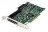
Connecting Internal SCSI Devices 5 Connect one end of the internal SCSI cable to the PowerDomain 2930 internal SCSI connector, as shown in the next figure. Blue or red stripe denotes Pin 1 Standard 50-pin internal SCSI cable (included in kit) Key Pin 1 marking Internal SCSI connector To connect more than two internal SCSI devices, you will need an internal SCSI cable with enough connectors for all devices. 6 Connect the other end of the cable to the last internal SCSI device, as shown in the next figure. This SCSI device must be terminated. (See Step 5 on page 11.) Make sure Pin 1 on the cable aligns with Pin 1 of the internal SCSI device connector. Pin 1 is usually designated by a "1" or small triangle. Terminated internal SCSI device Internal SCSI cable 8
-
 1
1 -
2
-
3
-
4
-
5
-
6
-
7
-
8
-
9
-
10
-
11
-
 12
12 -
 13
13 -
 14
14 -
 15
15 -
 16
16 -
 17
17 -
 18
18 -
 19
19 -
 20
20 -
 21
21 -
 22
22
 |
 |
