Airlink AICN500 User Manual - Page 6
Hardware Installation - camera
 |
View all Airlink AICN500 manuals
Add to My Manuals
Save this manual to your list of manuals |
Page 6 highlights
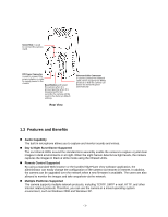
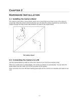
CHAPTER 2 HARDWARE INSTALLATION 2.1 Installing the Camera Stand The camera comes with a camera stand, which uses a swivel ball screw head to lock to the camera's screw hole. When the camera stand is attached, you can place the camera anywhere by mounting the camera through the three screw holes located in the base of the camera stand. The Camera Stand 2.2 Connecting the Camera to LAN Use the provided Ethernet cable to connect the camera to your local area network (LAN). When you connect the AC power adapter, the camera is powered on automatically. You can verify the power status from the Power LED on the front panel of the camera. Once connected, the Link LED starts flashing green light and the camera is on standby and ready for use now. -5-
-
 1
1 -
 2
2 -
 3
3 -
 4
4 -
 5
5 -
 6
6 -
 7
7 -
 8
8 -
 9
9 -
 10
10 -
 11
11 -
 12
12 -
13
-
14
-
15
-
16
-
17
-
18
-
19
-
20
-
21
-
22
-
23
-
24
-
25
-
26
-
27
-
28
-
29
-
30
-
31
-
32
-
33
-
34
-
35
-
36
-
37
-
38
-
39
-
40
-
41
-
42
-
43
-
44
-
45
-
46
-
47
-
48
-
49
-
50
-
51
-
52
-
53
 |
 |
