Alpine 9861 Owners Manual - Page 65
Installation - dva owners manual
 |
UPC - 793276500533
View all Alpine 9861 manuals
Add to My Manuals
Save this manual to your list of manuals |
Page 65 highlights
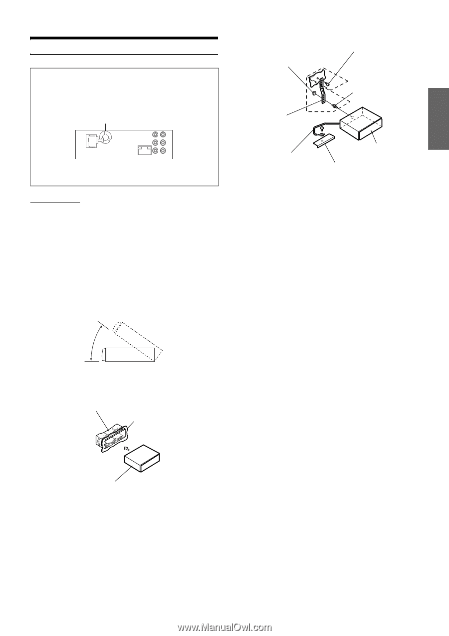
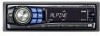
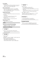
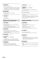
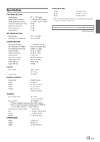
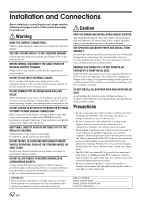
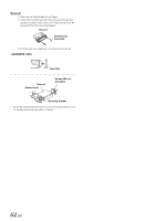
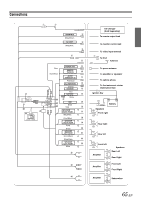
Installation Caution Do not block the unit's fan or heat sink, thus preventing air circulation. If blocked, heat will accumulate inside the unit and may cause a fire. Air ventilation hole (Rear side) Accessory List • Head unit 1 • Power cable 1 • Mounting sleeve 1 • Carrying case 1 • Bracket key 2 • Screw (M5x8 4 • RCA extension cable (Video) (2m 1 • Remote control 1 • Battery (CR2025 1 • Owner's Manual 1 set • The main unit must be mounted within 35 degrees of the horizontal plane, back to front. 2 Hex Nut (M5) Screw ** Bolt Stud Metal Mounting Strap * Ground Lead Chassis This unit Reinforce the head unit with the metal mounting strap (not supplied). Secure the ground lead of the unit to a clean metal spot using a screw (*) already attached to the vehicle's chassis. • For the screw marked **, use an appropriate screw for the chosen mounting location. Connect each input lead coming from an amplifier or equalizer to the corresponding output lead coming from the left rear of the DVA-9861. Connect all other leads of the DVA-9861 according to details described in the "Connections" section. 3 Slide the DVA-9861 into the dashboard until it clicks. This ensures that the unit is properly locked and will not accidentally come out from the dashboard. Install the Detachable Front Panel. Less than 35° 1 Mounting Sleeve (Included) Dashboard This unit Remove the Detachable Front Panel (refer to page 8). Slide mounting sleeve from main unit. (see "Removal" on page 64). Slide the mounting sleeve into the dashboard. 63-EN
-
 1
1 -
2
-
3
-
4
-
5
-
6
-
7
-
8
-
9
-
10
-
11
-
12
-
13
-
14
-
15
-
16
-
17
-
18
-
19
-
20
-
21
-
22
-
23
-
24
-
25
-
26
-
27
-
28
-
29
-
30
-
31
-
32
-
33
-
34
-
35
-
36
-
37
-
38
-
39
-
40
-
41
-
42
-
43
-
44
-
45
-
46
-
47
-
48
-
49
-
50
-
51
-
52
-
53
-
54
-
55
-
56
-
57
-
58
-
59
-
 60
60 -
 61
61 -
 62
62 -
 63
63 -
 64
64 -
 65
65 -
 66
66 -
 67
67 -
 68
68 -
 69
69 -
 70
70 -
71
-
72
-
73
-
74
-
75
-
76
-
77
-
78
-
79
-
80
-
81
-
82
-
83
-
84
-
85
-
86
-
87
-
88
-
89
-
90
-
91
-
92
-
93
-
94
-
95
-
96
-
97
-
98
-
99
-
100
-
101
-
102
-
103
-
104
-
105
-
106
-
107
-
108
-
109
-
110
-
111
-
112
-
113
-
114
-
115
-
116
-
117
-
118
-
119
-
120
-
121
-
122
-
123
-
124
-
125
-
126
-
127
-
128
-
129
-
130
-
131
-
132
-
133
-
134
-
135
-
136
-
137
-
138
-
139
-
140
-
141
-
142
-
143
-
144
-
145
-
146
-
147
-
148
-
149
-
150
-
151
-
152
-
153
-
154
-
155
-
156
-
157
-
158
-
159
-
160
-
161
-
162
-
163
-
164
-
165
-
166
-
167
-
168
-
169
-
170
-
171
-
172
-
173
-
174
-
175
-
176
-
177
-
178
-
179
-
180
-
181
-
182
-
183
-
184
-
185
-
186
-
187
-
188
-
189
-
190
-
191
-
192
-
193
-
194
-
195
-
196
-
197
-
198
-
199
-
200
-
201
-
202
-
203
-
204
-
205
-
206
-
207
-
208
 |
 |