Alpine 9861 Owners Manual - Page 69
System Example
 |
UPC - 793276500533
View all Alpine 9861 manuals
Add to My Manuals
Save this manual to your list of manuals |
Page 69 highlights
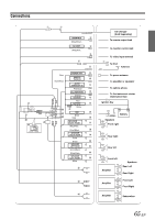
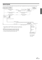
System Example Connect the Ai-NET compatible digital audio processor (Fiber optic compatible) and touch panel-compatible monitor/changer. System switch EQ/DIV Video output Lead (Yellow) Remote control input Lead (White/Brown) Video input terminal RCA Extension cable (Video) (Included) Touch panelcompatible monitor box (sold separately) Remote control output lead (White/Brown) Touch panelcompatible monitor (sold separately) Monitor control Lead (White/Pink) Monitor control Lead (White/Pink) To Digital output terminal Fiber optic Cable Fiber optic input terminal (for head unit) Ai-NET Cable Ai-NET output terminal • When the fiber optic compatible product is connected, it is necessary to set the mode of this unit. Refer to "Setting the Digital Output" (page 26) and set to ON. Please observe the following when using Fiber Optic Cable. • Be careful not to bend the Fiber Optic Cable at a sharp angle. • Do not coil the Fiber Optic Cable smaller than a 30 mm radius. • Do not place anything on top of the Fiber Optic Cable. Ai-NET compatible digital audio processor (sold separately) (Fiber optic compatible) Ai-NET Cable Fiber optic input terminal (for changer) * Fiber optic cable Ai-NET compatible CD changer (sold separately) *Only connect fiber optic compatible CD changer 67-EN
-
 1
1 -
2
-
3
-
4
-
5
-
6
-
7
-
8
-
9
-
10
-
11
-
12
-
13
-
14
-
15
-
16
-
17
-
18
-
19
-
20
-
21
-
22
-
23
-
24
-
25
-
26
-
27
-
28
-
29
-
30
-
31
-
32
-
33
-
34
-
35
-
36
-
37
-
38
-
39
-
40
-
41
-
42
-
43
-
44
-
45
-
46
-
47
-
48
-
49
-
50
-
51
-
52
-
53
-
54
-
55
-
56
-
57
-
58
-
59
-
60
-
61
-
62
-
63
-
 64
64 -
 65
65 -
 66
66 -
 67
67 -
 68
68 -
 69
69 -
 70
70 -
 71
71 -
 72
72 -
 73
73 -
 74
74 -
75
-
76
-
77
-
78
-
79
-
80
-
81
-
82
-
83
-
84
-
85
-
86
-
87
-
88
-
89
-
90
-
91
-
92
-
93
-
94
-
95
-
96
-
97
-
98
-
99
-
100
-
101
-
102
-
103
-
104
-
105
-
106
-
107
-
108
-
109
-
110
-
111
-
112
-
113
-
114
-
115
-
116
-
117
-
118
-
119
-
120
-
121
-
122
-
123
-
124
-
125
-
126
-
127
-
128
-
129
-
130
-
131
-
132
-
133
-
134
-
135
-
136
-
137
-
138
-
139
-
140
-
141
-
142
-
143
-
144
-
145
-
146
-
147
-
148
-
149
-
150
-
151
-
152
-
153
-
154
-
155
-
156
-
157
-
158
-
159
-
160
-
161
-
162
-
163
-
164
-
165
-
166
-
167
-
168
-
169
-
170
-
171
-
172
-
173
-
174
-
175
-
176
-
177
-
178
-
179
-
180
-
181
-
182
-
183
-
184
-
185
-
186
-
187
-
188
-
189
-
190
-
191
-
192
-
193
-
194
-
195
-
196
-
197
-
198
-
199
-
200
-
201
-
202
-
203
-
204
-
205
-
206
-
207
-
208
 |
 |
