Alpine KTP-190U Owners Manual - Page 3

Service Care, Specifications, Accessories, Installation Fig. 1, Fig. 2

Page 3 highlights

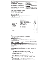
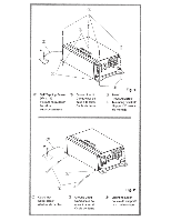
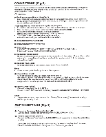
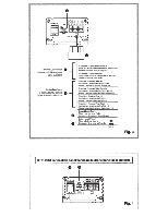
SERVICE CARE + IMPORTANT NOTICE This Amplifier has been type tested and found to comply with the limits for a Class B computing device in accordance with the specifications in Subpart J of Part 15 of FCC Rules. This equipment generates and uses radio frequency energy, and it must be installed and used properly in accordance with the manufacturer's instructions. • For European Customers Should you have any questions about warranty, please consult your store of purchase. • For Customers In other Countries IMPORTANT NOTICE Customers who purchase the product with which this notice is packaged, and who make this purchase in countries other than the United States of America and Canada, please contact your dealer for information regarding warranty coverage. SERIAL NUMBER: INSTALLATION DATE: INSTALLATION TECHNICIAN: PLACE OF PURCHASE: +IMPORTANT Please record the serial number of your unit in the space provided here and keep it as a permanent record. The serial number plate is located on the rear of the unit. SPECIFICATIONS Power Output THD+N SIN Ratio Frequency Response Damping Factor Input Impedance Input Sensitivity Crossover Dimensions Weight Ref: 14.4 V, 10, @ < 1% THD+N Ref: 14.4 V, 20, @ < 1% THD+N Ref: 10 W into 10 Ref: Rated Power into 10 Ref: 10 W into 20 Ref: Rated Power into 20 IHFA-wtd + AES-17, Ref: 1 W into 40 IHF A-wtd + AES-17, Ref: Rated Power into 40 +0 I -3 dB, Ref: 1 W into 10 Ref: 10 W into 40 at 100 Hz Ref: Rated Power into 10 Ref: Rated Power into 40 Selectable LPF@ -12 dB/oct (Not Defeatable) Width (with mount brackets) Width (w/o mount brackets) Height Depth 90W RMSX 1 60W RMS X 1 < 0.6°/o < 1.0°/o < 0.4°/o < 0 .8°/o > SOdB > 98dB 10- 120Hz > 200 > 10k0 5.9V 5.0V 60Hz, 80Hz, 120Hz 136mm (5-3/8") 111mm (4-3/8") 38mm (1-1 /2") 65mm (6-9/16") 0.4kg (0.91bs) NOTE: • For product improvemenJ, specificalions and design are subject to change witlwut notice. ACCESSORIES • Self Tapping Screws (M4 x 12 Spare Fuse (10A • lnpuVOutput!Power Wire Harness • Cable Tie 4 1 .... 1 . .... 2 INSTALLATION (Fig. 1) & (Fig. 2) With this amplifier, there are two options for installation. Depending on which is best for your target location, refer to instructions A or B below. &cAUTION • Caution on connection terminals/parts • Keep electrically conductive objects away from the unit's terminals/parts (power terminals, fuses, speaker output terminals, RCA connectors, etc.). Doing so prevents a possible short circuit and damage to the unit. MOUNTING A. Installation with mounting brackets 1. Using the amplifier as a template, mark the four mounting screw locations. 2. Make sure there are no objects behind the surface that may become damaged during drilling. 3. Drill the mounting screw holes. 4. Position the unit over the screw holes. 5. Fasten the unit down with the four self-tapping screws (M4 x 12). Refer to Fig. 1. B. Installation with chassis mounting loops 1. Push each of the included cable ties through the two mounting loops near each end on the bottom panel. 2. Use the cable ties to securely attach the amplifier to the vehicle's frame or chassis. Refer to Fig. 2. NOTE: To securely connect the growJd lead, use an already installed screw on the metal part ofthe vehicle (marked*). Be sure this is a good ground by checking continuity to the battery(- ) temJinal. As much aspossible cormect all equipment to the same ground point. These procedures will help eliminate noise.

  • 1
  • 2
  • 3
  • 4
  • 5
  • 6
  • 7
  • 8
  • 9
  • 10

SERVICE CARE
+
IMPORTANT NOTICE
SERIAL NUMBER:
This Amplifier has been type tested and found
to
comply with the limits for a Class B computing device in
INSTALLATION
DATE:
accordance with the specifications in Subpart
J
of Part
INSTALLATION TECHNICIAN:
15
of FCC Rules. This equipment generates and uses
PLACE OF PURCHASE:
radio frequency energy, and it must
be
installed and used
properly in accordance with the manufacturer's instructions.
+IMPORTANT
For European Customers
Please record the serial number of your unit in the
Should you have any questions about warranty, please
consult your store of purchase.
space provided here and keep it as a permanent
re
cord. The serial number plate is located on the
For Customers In other Countries
rear of the unit.
IMPORTANT NOTICE
Customers who
pur
chase the product with which this notice
is
packaged, and who make this purchase in countries
other than the United States of America and Canada,
please contact
your
dealer for information regarding
warranty coverage.
SPECIFICATIONS
Power Output
Ref: 14.4 V,
10,
@
<
1%
THD+N
Ref: 14.4 V,
20
, @
<
1% THD+N
Ref:
10
W into
10
Ref: Rated Power into
10
THD+N
Ref:
10
W into 20
Ref: Rated Power into 20
SIN Ratio
IHFA-wt
d + AES-
17,
Ref: 1 W into
40
IHF A-wtd + AES-
17,
Ref: Rated Power into
40
Frequency Response
+0
I
-3 dB, Ref: 1 W into
10
Damping Factor
Ref:
10
W into
40
at
100 Hz
Input Impedance
Ref: Rated Power into 10
Input Sensitivity
Ref: Rated Power into 40
Crossover
Selectable LP
F@
-
12
d
B/
oct (Not Defeatable)
Width (with mount brackets)
Dimensions
Width (w
/o
mount brackets)
Height
Depth
Weight
NOTE:
F
or
product improveme
nJ
,
spec
ificalions
and
design are subject to change
wi
tlwut
no
tice.
ACCESSORIES
• Self T
ap
ping Screws (M4 x 12)
..
·····················
··
··
·--
··
··········--······
• Spare Fuse (10A)
..............
..
....................
.....
....
..
................
_.
........
• lnpu
VO
utput!Power Wi
re
Harness
....................
..
_.
..
..
....................
.
• Cable Tie
..
...
..
.......
..........................
..
......
..
INSTALLATION (Fig. 1)
&
(Fig. 2)
90W
RMSX
1
60W RMS X 1
<
0.6°
/o
<
1.
0°/
o
<
0.4°
/o
<
0.
/o
>
SO
dB
> 98dB
10-
12
0Hz
> 200
> 10
k0
5.9V
5.0V
60Hz, 80Hz, 12
0H
z
136mm (5-3/8")
111mm
(4-
3/
8")
38mm (
1-1
/2")
65mm (6-9/16")
0.4kg (0.
91b
s)
...
..
............
...
.
..
....
..
........
.4
............
..
.
..
...... ..
..
.............
1
....
1
.
....
2
With this amplifier, there are two options for installatio
n.
Depending on which is best for your target location, refer
to instruct
io
ns A or B below.
&cAUTION
Caution on connection terminals/parts
• Keep elec
tr
ically conductive objects away from
th
e unit's terminals/parts (po
wer
terminals, fuses, s
peak
er
output terminal
s,
RCA connecto
rs
,
et
c.). Doing so
pr
events a possible short c
ir
cuit and damage to the uni
t.
MOUNTING
A. Installation with mounting brackets
1.
Using the amplifier as a templat
e,
mark the fo
ur
mounting screw locations.
2.
Make s
ur
e there are no objects
be
hind the surface that may become damaged during drilling.
3. Drill the mounting
sc
rew holes.
4. Position the unit over the screw holes.
5.
Fa
sten
th
e unit
do
wn with the fo
ur
se
lf-tapping
sc
rews (M4 x 12). Refer to Fig.
1.
B.
Installation with chassis mounting loops
1.
Pu
sh
eac
h of the included
ca
ble ties through the
tw
o mounting loops near each end on the bottom pane
l.
2.
Use the cable ties to secu
re
ly atta
ch
the amplifier to the vehicle's
fr
ame
or
ch
as
sis. Refer to Fig. 2.
NOTE:
To securely connect the growJd lead,
us
e
an
already i
ns
tall
ed
screw on the met
al
par
t
of
the vehicle
(marked*).
Be sure t
hi
s is a g
ood
ground
by
checking
co
ntinuity to the
battery(
-) temJinal.
As
mu
ch as possible
co
rm
ect
all
equipment to the same ground
point
. These
pro
cedures
will
help eliminate noise.