Alpine MRV-F900 Owners Manual
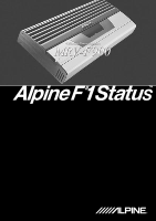
Alpine MRV-F900 - Amplifier Manual
 |
View all Alpine MRV-F900 manuals
Add to My Manuals
Save this manual to your list of manuals |
Alpine MRV-F900 manual content summary:
- Alpine MRV-F900 | Owners Manual - Page 1
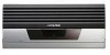
4 Channel Power Amplifier MRV-F900 - Alpine MRV-F900 | Owners Manual - Page 2
- Alpine MRV-F900 | Owners Manual - Page 3
ENGLISH R MRV-F900 4 Channel Power Amplifier • OWNER'S MANUAL Please read before using this equipment. • MODE D'EMPLOI Veuillez lire avant d'utiliser cet appareil. • MANUAL DE OPERACIÓN Léalo antes de utilizar este equipo. FRANÇAIS ESPAÑOL - Alpine MRV-F900 | Owners Manual - Page 4
- Alpine MRV-F900 | Owners Manual - Page 5
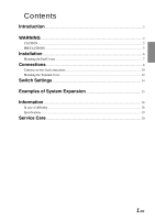
lead connections ...10 Mounting the Terminal Cover ...12 Switch Settings 14 Examples of System Expansion 15 Information ...18 In case of difficulty ...18 Specifications ...19 Service Care ...20 1-EN - Alpine MRV-F900 | Owners Manual - Page 6
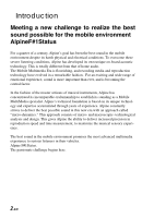
goal has been the best sound in the mobile environment despite its harsh physical and electrical conditions. To overcome these severe listening conditions, Alpine has developed its own unique on-board acoustic technology. This is totally different from that of home audio. The Mobile Multimedia Era - Alpine MRV-F900 | Owners Manual - Page 7
4 Channel Amplifier The MRV-F900 is designed to convey all the passion and impact of exceptional performances. The high fidelity circuitry of this 100W x 4-channel power amplifier, consists of high grade audio components. This combination produces beautiful harmonics, aiming at the ultimate in - Alpine MRV-F900 | Owners Manual - Page 8
WARNING WARNING This symbol means important instructions. Failure to heed them can result in CABLES TO BECOME ENTANGLED IN SURROUNDING OBJECTS. Arrange wiring and cables in compliance with the manual to prevent obstructions when driving. Cables or wiring that obstruct or hang up on places such - Alpine MRV-F900 | Owners Manual - Page 9
the MRV-F900 will not be installed in a location subjected to: • Direct sun and heat • High humidity and water • Excessive dust • Excessive vibrations Maintenance If you have problems, do not attempt to repair the unit yourself. Return it to your Alpine dealer or the nearest Alpine Service Station - Alpine MRV-F900 | Owners Manual - Page 10
locations, please contact your authorized Alpine dealer. 1. Using the amplifier as a template, mark the four screw locations. 2. Make sure there are no objects behind the surface that may become damaged during drilling. 3. Drill the screw holes. 4. Position the MRV-F900 over the screw holes, and - Alpine MRV-F900 | Owners Manual - Page 11
Mounting the End Covers • The product's appearance can be improved by mounting the end covers on the main unit after installation. • Mount the end covers after installing the main unit. 1 Mounting the brackets 1) Use the included machine screws 6 to mount the three included brackets 5 onto the side - Alpine MRV-F900 | Owners Manual - Page 12
from the amp directly to the Alpine dealer knows best about noise prevention measures so consult your dealer for further information. 1 RCA Input Jacks Connect these jacks to the line out leads on your head unit using RCA extension cables (sold separately). 2 Speaker Output Terminals The MRV-F900 - Alpine MRV-F900 | Owners Manual - Page 13
4 Battery Lead (Sold Separately) Be sure to add a fuse as close as possible to the MRV-F900's battery terminal. This fuse will protect your vehicle's electrical system and the MRV-F900 in case of a short circuit. If you need to extend this lead, the wire gauge should be AWG4 or larger. NOTES: • - Alpine MRV-F900 | Owners Manual - Page 14
Connections Cautions on wire lead connections • Use Power Supply wire sold at your dealer's store. • Refer to the description below for the proper procedure. If you are in doubt about how to make this connection, consult your dealer. 1 Check the wire size. NOTES: • Wire Size (Battery Lead, Ground - Alpine MRV-F900 | Owners Manual - Page 15
3 Slide the battery lead into the fuse block. • Slide the battery lead (sold separately) into the fuse block (supplied) as below: 1) Dismantle the fuse box. Turn the cap 1 counterclockwise. 2) Turn the hexagon screw 3 of the fuse terminal 2 with a hexagon wrench (supplied). 3) Remove the rubber ring - Alpine MRV-F900 | Owners Manual - Page 16
Connection Mounting the Terminal Cover • The product's appearance can be improved by mounting the terminal cover on the main unit after installation. • Mount the terminal cover after the connections have been made and you have checked that operation is normal. 1 Open the door. 1) Use the included - Alpine MRV-F900 | Owners Manual - Page 17
3 Fastening the door 1) Close the door p. 2) Mount the door p using the two original hexagonal screws q. * Tighten the screws securely so that they do not come loose due to vibrations while the vehicle is moving. NOTES: • Be sure to fasten the door. Failure to do so may lead to malfunction. • The - Alpine MRV-F900 | Owners Manual - Page 18
to the "BRIDGED" position. MODE 13 Status indicator Amplifier status can be confirmed with the indicator. • Protection indicator (PROTECTION) Blue Red Condition Light Amplifier circuit is normal. Solution Light Amplifier circuit is abnormal. Contact your authorized Alpine dealer. 14-EN - Alpine MRV-F900 | Owners Manual - Page 19
Examples of System Expansion • SYSTEM A (4ch input, 4ch output) 15 Battery Lead* 80A To the vehicle's battery Ground Lead SPEAKER L R SPEAKER L R + -+ - + -+ - CH-1/ CH-2 CH-3/ CH-4 NORMAL BRIDGED MODE NORMAL BRIDGED MODE CH-1 INPUT CH-2 + BRIDGED - + CH-1 - + CH-2 - SPEAKER - Alpine MRV-F900 | Owners Manual - Page 20
input, 11ch output) CDA-7990 PXA-H900 FUSE 15A POWER SUPPLY BATTERY GND CENTER SUBWOOFER REAR FRONT LOW FRONT MID FRONT HIGH (L) GUIDE INPUT OUTPUT (R) Front Tweeter Output (L) 14 Front Tweeter Output (R) Front Mid Range Output (L) 14 Front Mid Range Output (R) Front Mid Bass Output - Alpine MRV-F900 | Owners Manual - Page 21
15 80A BGR To the vehicle's battery To Ground To Remote Turn-On Lead Front Tweeter L R Front Mid L R BGR + - + - + -+ - CH-1 INPUT CH-2 + BRIDGED - + CH-1 - + CH-2 - SPEAKER OUTPUT BATTERY GND RENOTE POWER SUPPLY + BRIDGED - + CH-3 - + CH-4 - CH-3 SPEAKER OUTPUT INPUT CH-4 - Alpine MRV-F900 | Owners Manual - Page 22
case of difficulty If you encounter a problem, please review the items in the following checklist. This guide will help you isolate the problem if the unit is at fault. Otherwise, make sure the rest of your system is properly connected or consult your authorized Alpine dealer. Set does not operate - Alpine MRV-F900 | Owners Manual - Page 23
Tube 1 SET Fuse Box 1 Fuse (80A 1 Due to continuous product improvement, specifications and design are subject to change without notice. The illustrations included in these instructions may appear different from the actual product due to printing conditions. 19-EN - Alpine MRV-F900 | Owners Manual - Page 24
Service Care N For North American Customers IMPORTANT NOTICE This Amplifier has been type tested and found to comply and it must be installed and used properly in accordance with the manufacturer's instructions. SERIAL NUMBER: INSTALLATION DATE: INSTALLATION TECHNICIAN: PLACE OF PURCHASE: IMPORTANT - Alpine MRV-F900 | Owners Manual - Page 25
MEMO - Alpine MRV-F900 | Owners Manual - Page 26
MEMO - Alpine MRV-F900 | Owners Manual - Page 27
- Alpine MRV-F900 | Owners Manual - Page 28
INC. 1-1-8 Nishi Gotanda, Shinagawa-ku, Tokyo 141-0031, Japan Phone 03-5496-8231 ALPINE ELECTRONICS OF AMERICA, INC. 19145 Gramercy Place, Torrance, California 90501, U.S.A. Phone 1-800-ALPINE-1 (1-800-257-4631) ALPINE ELECTRONICS OF CANADA, INC. 7300 Warden Ave., Suite 203, Markham, Ontario L3R 9Z6
-
 1
1 -
 2
2 -
 3
3 -
 4
4 -
 5
5 -
 6
6 -
 7
7 -
8
-
9
-
10
-
11
-
12
-
13
-
14
-
15
-
16
-
17
-
18
-
19
-
20
-
21
-
22
-
23
-
24
-
25
-
26
-
27
-
28
 |
 |

4 Channel Power Amplifier
4 Channel Power Amplifier