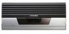
Alpine MRV-F900 Owners Manual - Page 10
Installation - f 1 mrv
 |
View all Alpine MRV-F900 manuals
Add to My Manuals
Save this manual to your list of manuals |
Page 10 highlights
Installation Due to the high power output of the MRV-F900, considerable heat is produced when the amplifier is in operation. For this reason, the amplifier should be mounted in a location which will allow for free circulation of air, such as inside the trunk. For alternate installation locations, please contact your authorized Alpine dealer. 1. Using the amplifier as a template, mark the four screw locations. 2. Make sure there are no objects behind the surface that may become damaged during drilling. 3. Drill the screw holes. 4. Position the MRV-F900 over the screw holes, and secure with four self-tapping screws. NOTE: To securely connect the ground lead, use an already installed screw on the metal part of the vehicle (marked (#)). Be sure this is a good ground by checking continuity to the battery (-) terminal. As much as possible connect all equipment to the same ground point. These procedures will help eliminate noise. 1 Self-Tapping Screws (M4 x 20) 2 Ground Lead 3 Chassis 4 Holes 1 2 # 3 4 6-EN Fig. 1
-
 1
1 -
2
-
3
-
4
-
 5
5 -
 6
6 -
 7
7 -
 8
8 -
 9
9 -
 10
10 -
 11
11 -
 12
12 -
 13
13 -
 14
14 -
 15
15 -
16
-
17
-
18
-
19
-
20
-
21
-
22
-
23
-
24
-
25
-
26
-
27
-
28
 |
 |
