Amana AEP222VA Installation Instruction
Amana AEP222VA Manual
 |
View all Amana AEP222VA manuals
Add to My Manuals
Save this manual to your list of manuals |
Amana AEP222VA manual content summary:
- Amana AEP222VA | Installation Instruction - Page 1
RANGE with Standard Clean Oven Table of Contents RANGE SAFETY 2 INSTALLATION REQUIREMENTS 3 Tools and Parts 3 Location Requirements 3 Electrical Requirements 5 INSTALLATION INSTRUCTIONS 6 Unpack Range 6 Install Anti-Tip Bracket 6 Electrical Connection 7 Verify Anti-Tip Bracket Is - Amana AEP222VA | Installation Instruction - Page 2
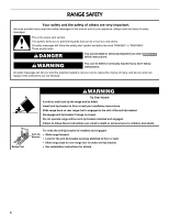
important. We have provided many important safety messages in this manual and on your appliance. Always read and obey all safety messages. This is the reduce the chance of injury, and tell you what can happen if the instructions are not followed. Range Foot WARNING Tip Over Hazard A child or - Amana AEP222VA | Installation Instruction - Page 3
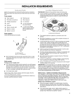
INSTALLATION REQUIREMENTS Tools and Parts Gather the required tools and parts before starting installation. Read and follow the instructions provided with any tools listed here be used in a mobile home installation. The appliance wiring will need to be revised. See "Electrical Connection" section. 3 - Amana AEP222VA | Installation Instruction - Page 4
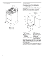
installing a range hood or microwave hood combination above the range, follow the range hood or microwave hood combination installation instructions for dimensional clearances above the cooktop surface. B D C F D A E B C A. 36" (91.4 cm) B. 19½" (49.5 cm) C. 24½" (62.2 cm) D. 42" (106.7 cm - Amana AEP222VA | Installation Instruction - Page 5
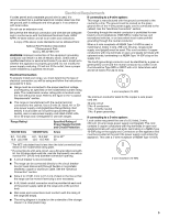
electric shock. Check with a qualified electrician or service technician if you are in doubt as to whether the appliance is properly grounded. Do not modify the power the type of electrical connection you will be using and follow the instructions provided for it here. ■ Range must be connected to the - Amana AEP222VA | Installation Instruction - Page 6
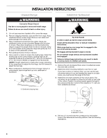
bottom under range. Remove oven racks and parts package from inside oven. 3. Take 4 cardboard them lengthwise on the floor behind the range to support the range when it is laid on its back bracket installed and engaged. Failure to follow these instructions can result in death or serious burns to - Amana AEP222VA | Installation Instruction - Page 7
new 40 amp power supply cord. Plug into a grounded outlet. Failure to follow these instructions can result in death, fire, or electrical shock. Electrical Shock Hazard Disconnect power before servicing. Use 8 gauge copper or 6 gauge aluminum wire. Electrically ground range. Failure to follow these - Amana AEP222VA | Installation Instruction - Page 8
back panel and screws on rear of range. 5. Complete installation following instructions for your type of electrical connection: 4-wire (recommended) 3-wire vehicles ■ In an area where local codes prohibit grounding through the neutral 1. Part of metal ground strap must be cut out and removed. A C B - Amana AEP222VA | Installation Instruction - Page 9
2. Use Phillips screwdriver to remove the ground-link screw from the back of the range. Save the ground-link screw and the end of the ground-link under the screw. 3. Feed the power supply cord through the strain relief on the cord/conduit plate on bottom of range. Allow enough slack to easily attach - Amana AEP222VA | Installation Instruction - Page 10
New branch-circuit installations (1996 NEC) ■ Mobile homes ■ Recreational vehicles ■ In an area where local codes prohibit grounding through the neutral 1. Part of metal ground strap must be cut out and removed. A B C A. Metal ground strap B. Discard C. Ground-link screw 2. Use Phillips screwdriver - Amana AEP222VA | Installation Instruction - Page 11
3-wire connection: Direct Wire Use this method only if local codes permit connecting ground conductor to neutral supply wire. 1. Pull the conduit through the strain relief on cord/conduit plate on bottom of range. Allow enough slack to easily attach the wiring to the terminal block. A 3. Use ³⁄₈" - Amana AEP222VA | Installation Instruction - Page 12
the "Assistance or Service" section of the Use and Care Guide to contact service. Level Range 1. Installation 1. Check that all parts are now installed. If there is an extra part, go back through the supply is connected. ■ See "Troubleshooting" in the Use and Care Guide. A. Oven indicator light 2.
-
 1
1 -
 2
2 -
 3
3 -
 4
4 -
 5
5 -
 6
6 -
 7
7 -
8
-
9
-
10
-
11
-
12
 |
 |

INSTALLATION INSTRUCTIONS
20" (50.8 CM) FREESTANDING ELECTRIC RANGE
with Standard Clean Oven
Table of Contents
RANGE SAFETY
.............................................................................
2
INSTALLATION REQUIREMENTS
................................................
3
Tools and Parts
............................................................................
3
Location Requirements
................................................................
3
Electrical Requirements
...............................................................
5
INSTALLATION INSTRUCTIONS
..................................................
6
Unpack Range
..............................................................................
6
Install Anti-Tip Bracket
.................................................................
6
Electrical Connection
...................................................................
7
Verify Anti-Tip Bracket Is Installed and Engaged
......................
11
Level Range
................................................................................
12
Complete Installation
.................................................................
12
Check Operation
........................................................................
12
W10459122A
IMPORTANT:
Save for local electrical inspector's use.